Water-gas composite energy-storage power generation system and method

An energy storage power generation, water gas technology, applied in the direction of hydropower generation, engine components, machines/engines, etc., can solve the problems of cavitation damage, low energy storage efficiency, reducing the efficiency and durability of the energy storage power generation system

Active Publication Date: 2019-06-18
国家电投集团综合智慧能源科技有限公司 +1
View PDF9 Cites 1 Cited by
  • Summary
  • Abstract
  • Description
  • Claims
  • Application Information

AI Technical Summary

Problems solved by technology

[0005] In the existing water-gas composite energy storage power generation system, the gas is only compressed to a single pressure value during energy storage, and the gas energy cannot be utilized in steps, and the energy storage efficiency is low; and the existing water-gas composite energy storage power generation system The gas

Method used


Image

  • Water-gas composite energy-storage power generation system and method
  • Water-gas composite energy-storage power generation system and method

Examples


Embodiment 1

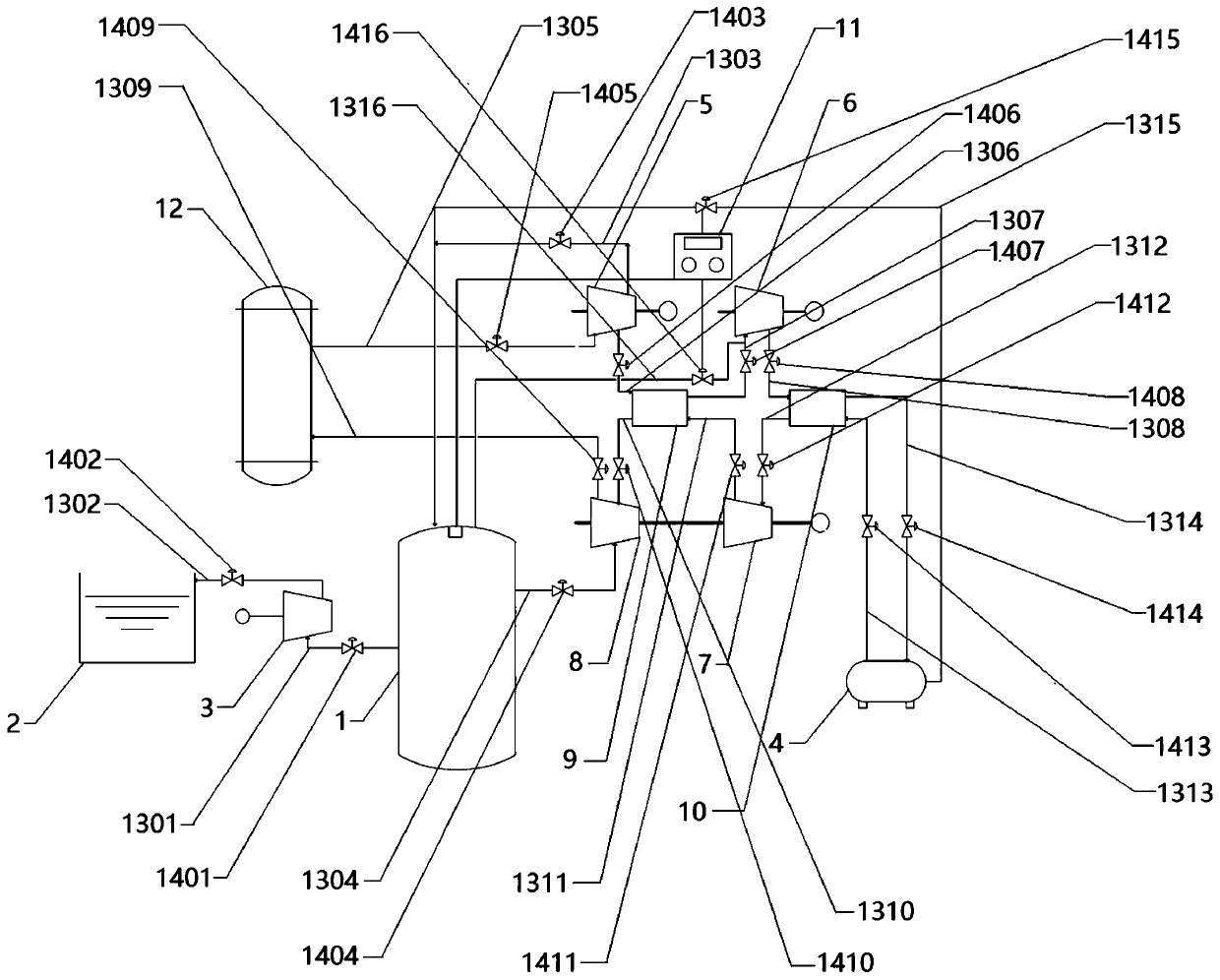
[0106] An embodiment of the present invention provides a water-gas composite energy storage power generation system, such as figure 1 As shown, it includes: pressure water tank 1, pool 2, water turbine 3, high-pressure nitrogen storage tank 4, primary compressor 5, secondary compressor 6, primary expander 7, secondary expander 8, low-temperature heat accumulator 9 , high-temperature accumulator 10, atmospheric pressure nitrogen storage tank 12, a plurality of communication pipelines 13 and a plurality of valves 14, wherein:

[0107] The first port of the water turbine 3 communicates with the pool 2 through the second communication pipe 1302 , and the second communication pipe 1302 is provided with a second valve 1402 .

[0108] The second port of the water turbine 3 communicates with the two-way port of the pressure water tank 1 through the first communication pipe 1301, and the first valve 1401 is arranged on the first communication pipe 1301. The two-way port of the pressure...

Embodiment 2

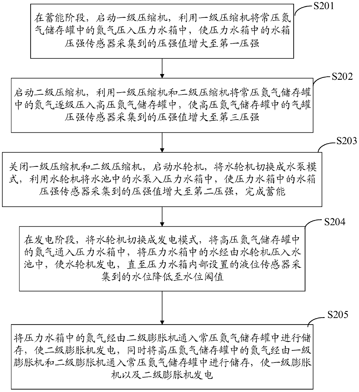
[0149] An embodiment of the present invention provides a water-gas composite energy storage power generation method, such as figure 2 As shown, the method includes steps S201, S202, S203, S204 and S205, wherein:

[0150] The whole method is divided into two main processes. The first process is used in the low power consumption period, that is, the power generation is greater than the power consumption, and the excess electric energy needs to be converted into other forms of energy for storage, including steps S201, S202 and S203; The second process is used in the peak period of power consumption, that is, the power consumption is greater than the power generation, and the energy stored in the first process needs to be used for power generation, including steps S204 and S205.

[0151] The first process is described in detail below:

[0152] In step S201, in the energy storage stage, start the primary compressor 5, and use the primary compressor 5 to press the nitrogen in the ...


PUM


Abstract

The invention provides a water-gas composite energy-storage power generation system and method, and belongs to the field of peak shaving of power grids. The system comprises a pressure water tank (1),a water pool (2), a water turbine (3), a high-pressure nitrogen storage tank (4), a first-stage compressor (5), a second-stage compressor (6), a first-stage expansion machine (7), a second-stage expansion machine (8), a low-temperature heat accumulator (9), a high-temperature heat accumulator (10), a normal-pressure nitrogen storage tank (12), multiple communicating pipelines (13) and multiple valves (14). The air is replaced by nitrogen which is not dissolved in water easily, so that the cavitation damage to blades of a hydro-generator is avoided, and the durability of the energy-storage power generation system is improved; and gradient utilization is performed on the energy of compressed nitrogen during energy storage, one part of low-pressure nitrogen is stored in the pressure water tank (1), and the other part of high-pressure nitrogen is stored in the high-pressure nitrogen storage tank (4), so that the nitrogen under different pressure intensity can be utilized sufficiently, andthe energy storage efficiency of the energy-storage power generation system can be improved.

Description

technical field [0001] The invention belongs to the technical field of power grid peak regulation, and in particular relates to a water-gas composite energy storage power generation system and method. Background technique [0002] With the rapid development of renewable energy and the deepening of the contradiction between power resources and power loads in various regions of our country, it is often necessary to adjust the peak of the power grid and store energy during the low power consumption period so as to discharge during the peak power consumption period. Therefore, energy storage systems are getting more and more attention in engineering applications. At this stage, the only energy storage system that is really used on a large scale in my country is pumped storage. However, pumped storage has very strict requirements on natural geographical conditions and water resources. [0003] Considering that compressed gas energy storage has little dependence on natural geogra...

Claims


Application Information

Patent Timeline
IPC IPC(8): F03B13/06F03B3/10F01K27/00
CPCY02E10/20Y02E60/16
Inventor 韩磊贲岳侯付彬董芮廷王焕然张贤
Owner 国家电投集团综合智慧能源科技有限公司
Why Eureka
Try Eureka