
Dam gate bottom plate downstream connection section body shape and setting method thereof

A gate floor and connecting section technology, applied in special data processing applications, complex mathematical operations, instruments, etc., can solve problems such as building damage, wall detachment, negative pressure, etc., to ensure structural safety and service life, and avoid empty space. Erosion damage, high promotional value effect

Active Publication Date: 2017-12-08
CHINA POWER CONSRTUCTION GRP GUIYANG SURVEY & DESIGN INST CO LTD
View PDF1 Cites 2 Cited by
  • Summary
  • Abstract
  • Description
  • Claims
  • Application Information

AI Technical Summary

Problems solved by technology

However, according to engineering practice experience, if the gradient of the slope section is relatively gentle, the smooth connection between the second conjugate water depth and the downstream deep tailwater cannot be achieved; if the slope section is steep, under the condition of high-speed water flow, water flow is likely to occur at the beginning of the slope section When the cavitation water flow with a large number of cavitation bubbles in the low-pressure area flows through the downstream high-pressure area, the cavitation bubbles will collapse, and the solid side wall will be continuously affected. The continuous impact makes cavitation pits on the surface
If it is not repaired and treated in time, the intensity of cavitation will be further enhanced, and the depth and range of cavitation pits will continue to expand, which will affect the service life of hydraulic structures and even cause damage to structures.

Method used


Image

  • Dam gate bottom plate downstream connection section body shape and setting method thereof

Examples


Embodiment Construction

[0021] The present invention will be described in further detail below in conjunction with the accompanying drawings and embodiments.

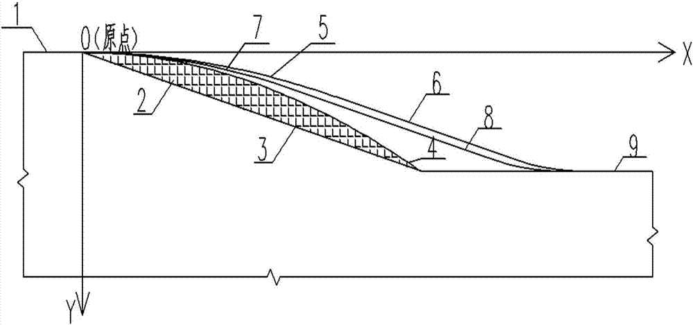
[0022] Such as figure 1 As shown, the number mark 2 represents the water flow off the wall area, the number mark 1 represents the bottom plate of the flat bottom gate, and the number mark 9 represents the bottom plate of the stilling basin. According to the prior art, the slope section is designed as a straight line slope section, such as figure 1 Indicated by number 3.

[0023] The preliminary drafting method of the curved slope section of the bottom plate of the flat-bottomed sluice of the present invention is realized according to the following steps:

[0024] Step 1: Collect hydrological data of the dam site area, including design flood standards, water level flow relationship;

[0025] Step 2: According to the hydrological data and the orifice size of the sluice gate, calculate the single-width discharge of the sluice under the design ...


PUM


Abstract

The invention discloses a dam gate bottom plate downstream connection section body shape and a setting method thereof. The method comprises the steps of collecting hydrological data of a dam site region; calculating gate-passing discharge per unit width under a design flood standard in each working condition; selecting maximum gate-passing discharge per unit width to calculate an average flow velocity vH of the fracture surface at the beginning of a slope section; by adopting a Lagrangian liquid motion method, establishing a coordinate system by taking the beginning of the slope section as a coordinate origin, and obtaining a reference curve equation; according to the reference curve equation, setting a starting curve by considering the situation that water flow separated from a wall is not generated on a flow-passing surface; and through verification of a hydraulic model experiment and actual conditions of engineering, determining the final dam gate bottom plate downstream connection section body shape. The designed body shape avoids the situation that the water flow generates a region separated from the wall in conventional slope section design, so that the flow state of the water flow at the beginning of the slope section is stable and the effect of hydraulic jump energy dissipation is improved; and the slope section is prevented from being subjected to cavitation damage.

Description

technical field [0001] The invention belongs to the application technical field of water conservancy and hydropower engineering, and in particular relates to a method for drawing up the body shape of the downstream connection section of the bottom plate of a dam gate. Background technique [0002] In the design of the sluice, the design of the underflow energy dissipator is an important content. The function of the bottom flow energy dissipator is to eliminate residual energy by generating a hydraulic jump with a certain degree of submersion under the sluice, and the position of the hydraulic jump occurrence point is greatly affected by the change of the tail water level. In engineering practice, a section is set in front of the stilling basin The slope (generally not steeper than 1 / 4) can effectively control the location of the hydraulic jump point and solve the problem of too deep downstream tail water. However, according to engineering practice experience, if the gradien...

Claims


Application Information

Patent Timeline
Patent Type & Authority Applications(China)
IPC IPC(8): G06F17/50G06F17/11
CPCG06F17/11G06F30/13G06F30/20Y02A10/40
Inventor 房彬张毅驰雷声军居浩高传彬李刚何建峰郑晓晖
Owner CHINA POWER CONSRTUCTION GRP GUIYANG SURVEY & DESIGN INST CO LTD
Learn More