Method of controlling a vehicle, apparatus for controlling the same, transmission and apparatus for controlling the same

a technology for controlling vehicles and transmissions, applied in mechanical devices, instruments, transportation and packaging, etc., can solve the problems of difficult operation of the clutch and the accelerator at starting, large shock generation, and rapid increase in the rotation speed of the engine, so as to prevent the time required, improve the shift quality, and improve the effect of the quality of the shi

Inactive Publication Date: 2007-05-01
HITACHI LTD
View PDF17 Cites 14 Cited by
  • Summary
  • Abstract
  • Description
  • Claims
  • Application Information

AI Technical Summary

Benefits of technology

[0006]A first object of the present invention is to provide a vehicle control method, a vehicle control apparatus, a transmission, and a transmission control apparatus, which can improve the shift quality by preventing the time required to synchronize the rotation speeds from becoming long or short even if the machine difference between assist clutches or the deterioration with age occurs, and improve the shift quality by suppressing the time required to synchronize the rotation speeds from becoming long or short even if the change in characteristics due to the replacement of a clutch or the changing of operating fluid.

Problems solved by technology

However, coordination of the clutch and the accelerator at starting is difficult to be operated.
If the coordination of the clutch and the accelerator at starting is not operated well, a large shock is generated at engaging the clutch, or rotation speed of the engine may be rapidly increased when the clutch pressure is insufficient, that is, what is called as a blowing-up phenomenon occurs.
Further, when the clutch is suddenly engaged while rotation speed of the engine is insufficient, or when the vehicle is started to run on an uphill, the engine may be stopped, that is, what is called as engine stopping occurs.
However, a driver sometimes feels incongruity because suspension of driving torque occurs by disengaging and engaging of the clutch in the control at shifting gear in the conventional automatized MT (the automatized manual transmission).
However, it was revealed that the time required to synchronize these rotation speeds gets longer in consequence of the change in characteristics due to the machine difference between assist clutches or the deterioration with age, the change in characteristics due to the replacement of the assist clutch or the changing of operating fluid, or the machine difference between engines or the deterioration with age, and shift quality is deteriorated by the sluggish feeling of shifting.
Moreover, the striking-feeling occurs if the time required to synchronize the rotation speeds is occasionally shortened, and shift quality decreases.

Method used


Image

  • Method of controlling a vehicle, apparatus for controlling the same, transmission and apparatus for controlling the same
  • Method of controlling a vehicle, apparatus for controlling the same, transmission and apparatus for controlling the same
  • Method of controlling a vehicle, apparatus for controlling the same, transmission and apparatus for controlling the same

Examples


first embodiment

[0116]The configuration and the operation of a vehicle control apparatus according to the present invention will be described below, referring to FIG. 1 to FIG. 20.

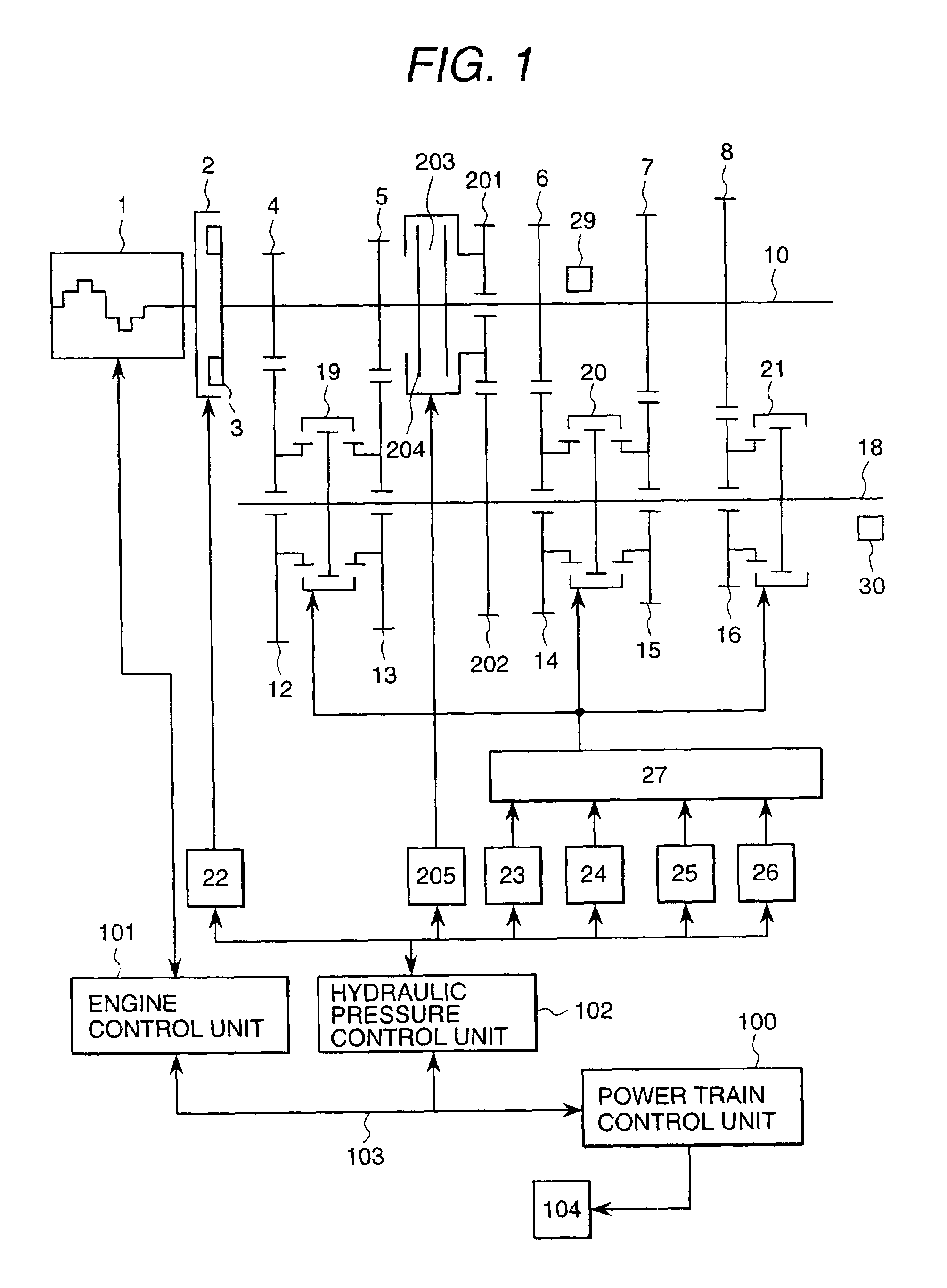
[0117]Initially, a first configuration example of the system of controlling the vehicle of the present embodiment will be described, referring to FIG. 1.

[0118]FIG. 1 is a system diagram showing the first configuration example of the system of controlling the vehicle of the first embodiment of the present invention.

[0119]An engine 1 comprises an engine rotation speed sensor, not shown, for measuring rotation speed of the engine 1; an electronic control throttle (not shown in the figure) for controlling engine torque; and a fuel injector (not shown in the figure) for injecting an amount if fuel corresponding to an amount of intake air. An engine control unit 101 can control torque of the engine 1 with high accuracy by operating the amount of intake air, the amount of fuel, ignition timing and so on. As the fuel injector, th...

second embodiment

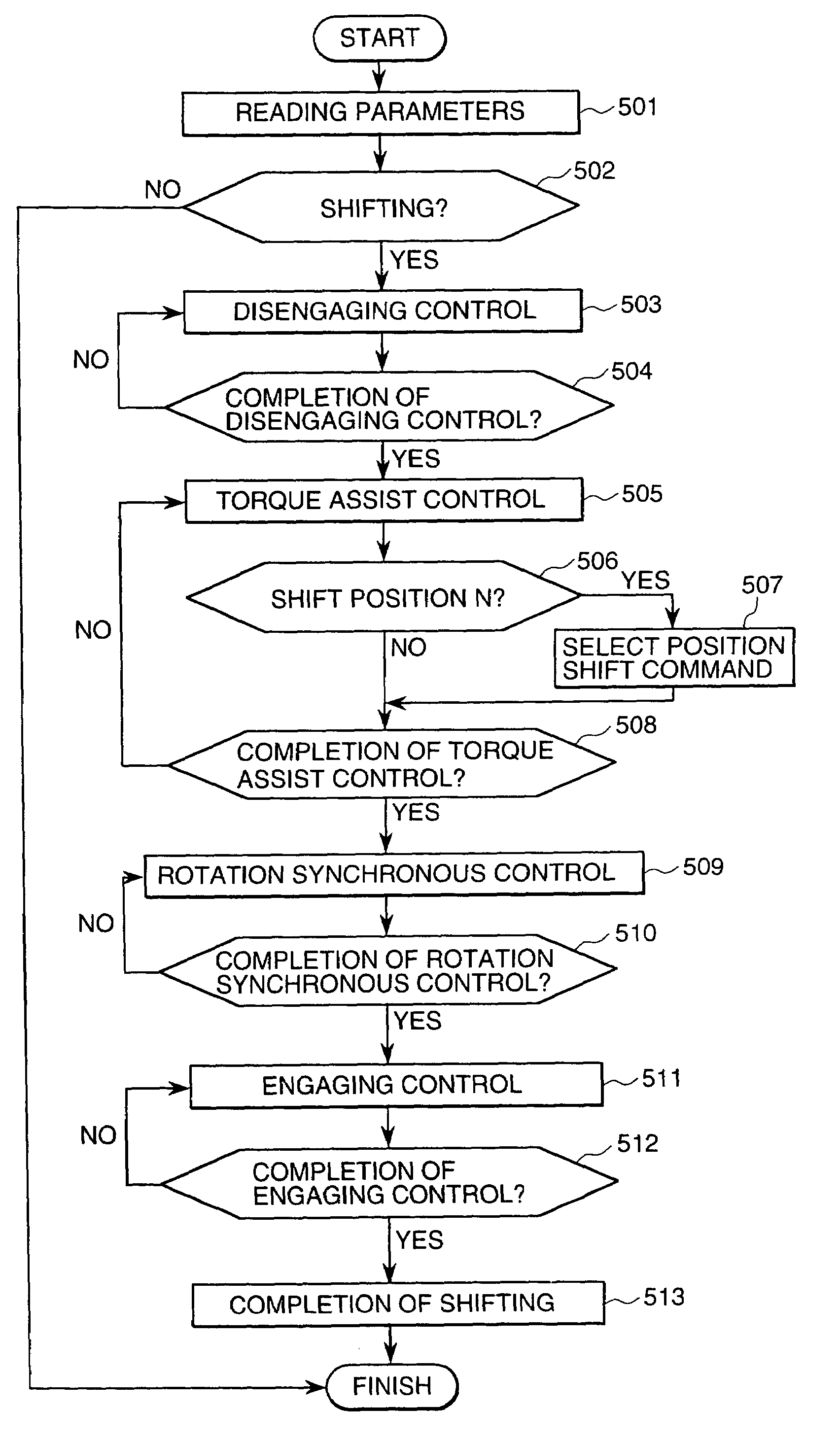
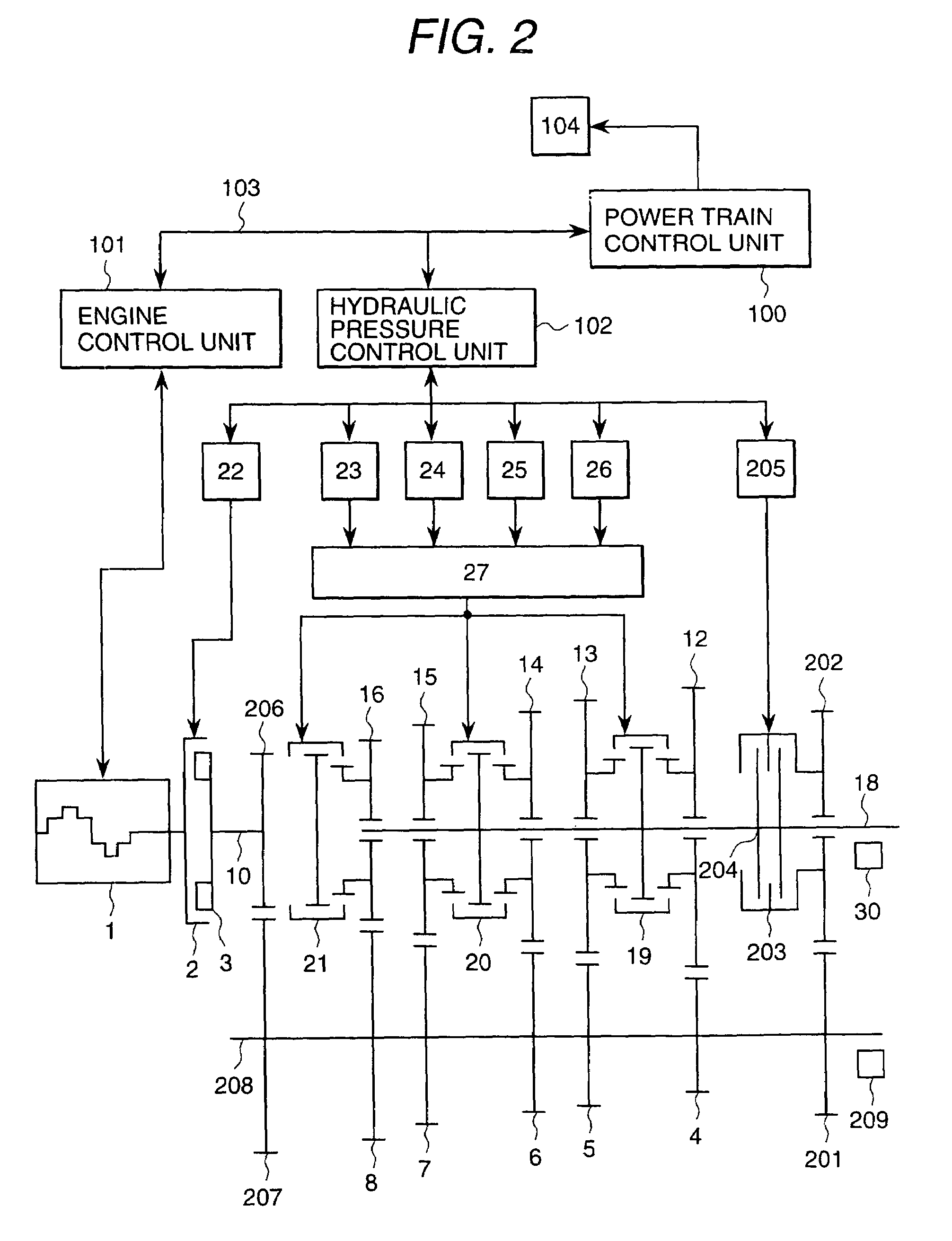
[0259]Here, the configuration of a vehicle control apparatus is similar to that shown in FIG. 1 or FIG. 2. The engaging relationship between the clutch and the driven gear in the present embodiment is similar to that shown in FIG. 3. The input-output signal relationship by the communication means 103 among the power train control unit 100, the engine control unit 101 and the hydraulic pressure control unit 102 in the control apparatus of the vehicle according to the present embodiment is similar to that shown in FIG. 4. The overall control content of the vehicle control apparatus according to the present embodiment are similar to those shown in FIG. 5. The content of the timer indicative of the elapsed time of the shift control by the vehicle control apparatus according to the present embodiment are similar to those shown in FIG. 6. The control content of the disengaging control phase of Step 503 of the shift control by the vehicle control apparatus according to the present embodim...

third embodiment

[0308]FIG. 28 is a flow chart showing the content of the correction value calculating processing in the shift control by the vehicle control apparatus according to the present invention. FIG. 29 is a flow chart showing the content of the torque difference integral value calculating processing shown in FIG. 28. FIG. 30 is a flow chart showing the content of the learning correction value calculating processing shown in FIG. 28.

[0309]The content of the correction calculating processing to be described below are programmed in the computer 100c of the power train control unit 100, and repetitively executed in a predetermined cycle. That is, the processing from Step 2801 and 2802 described below is executed by the power train control unit 100.

[0310]The correction value calculating processing in Step 514 shown in FIG. 5 is composed of the torque difference integral value calculating processing in Step 2801 and the learning correction value calculating processing in Step 2802 in this embodi...


PUM


Abstract

Power train control unit 100 controls friction clutch 203 when shifting from one cogwheel row to the other cogwheel row, sets the target synchronous rotation speed based on the output rotation speed of a transmission and parameters indicative of the state of engine 1 or the transmission, and sets the command value to the friction clutch so that the input rotation speed can be synchronized with the target synchronous rotation speed. Control unit 100 sets the target shifting required time based on parameters indicative of the state of engine 1 or the transmission, and corrects the command value to the friction clutch so that the required shift time can approach the above target shift required time.

Description

BACKGROUND OF THE INVENTION[0001]The present invention relates to a method of controlling a vehicle, a vehicle control apparatus, a transmission, and an apparatus for controlling a transmission, and particularly to a method of controlling a vehicle, a vehicle control apparatus, a transmission, and a transmission control apparatus, which are suitable to control the automatic transmission in the vehicle.[0002]A vehicle of a manual transmission type is excellent in fuel economy compared to a vehicle mounting a transmission using a torque converter. However, coordination of the clutch and the accelerator at starting is difficult to be operated. If the coordination of the clutch and the accelerator at starting is not operated well, a large shock is generated at engaging the clutch, or rotation speed of the engine may be rapidly increased when the clutch pressure is insufficient, that is, what is called as a blowing-up phenomenon occurs. Further, when the clutch is suddenly engaged while ...

Claims


Application Information

Patent Timeline
Patent Type & Authority Patents(United States)
IPC IPC(8): G06F19/00B60W10/02B60W10/06B60W10/11B60W10/113B60W30/18B60W30/19F16H59/40F16H59/42F16H61/04F16H61/06F16H61/08F16H61/68F16H61/684F16H61/688F16H63/50G06F17/00
CPCB60W10/06B60W10/11B60W10/113B60W30/18B60W30/19F16H61/0437F16H61/061B60W10/02B60K2741/225Y10T477/69335B60W2510/1015B60W2510/104B60W2710/1011B60W2710/1038F16H61/08F16H61/688F16H63/46F16H2061/0425F16H2306/44F16H2306/52Y10T477/6425Y10T477/75B60W10/10B60W30/1819B60W2050/0012
Inventor MATSUMURA, TETSUOOZAKI, NAOYUKIFUJIMOTO, KINYAKUROIWA, HIROSHIOKADA, TAKASHI
Owner HITACHI LTD
Why Eureka
Try Eureka