Device for filling a container with a plurality of objects

a technology for containers and objects, applied in the direction of conveying parts, stacking articles, solid materials, etc., can solve the problems of slack filling, high cost, and inability to meet the requirements of high-speed operation, and achieve the effect of facilitating rapid diagnosis of the cause of the problem, high maximum operating speed, and high operational reliability of packing machinery

Inactive Publication Date: 2007-05-08
MFG SOLUTIONS
View PDF18 Cites 22 Cited by
  • Summary
  • Abstract
  • Description
  • Claims
  • Application Information

AI Technical Summary

Benefits of technology

[0022]Such a device possesses significant advantages over the prior art, as it provides a guided entry to a controlled size cavity within the container, where the cavity dimensions may be set slightly larger than the object, and may be set to a consistent size. This greatly assists in allowing a repeatable and consistent deposition of objects that may themselves have inconsistent dimensions and shapes.
[0040]The core area of application of the present invention is food products packed in objects or pouches that are required to be packed on end within a container, and which have sufficient weight to enable the falling object or pouch to be guided with reasonable consistency. This invention has application where insertion rates are not especially high, for example less than about 140 items per minute, but where an automated packing method is desired. The invention is particularly suitable for food products because in the food industry both the type of product to be packed and the package sizes tend to be changed regularly, placing a premium on flexibility of operation and an ability to handle variable packages.

Problems solved by technology

Most of the machines available to place bags or pouches in a packing case with a vertical orientation tend to be large, expensive and capable of high speed operation.
However, the mechanism to do this includes insertion of the end of a conveyor mechanism into the case which, when withdrawn from the case after filling, leaves an unused void in the case that compromises the volume efficiency of the operation, otherwise known as ‘slack fill’.
DE 19917657, which fills the case in a different direction and uses different methods to prepare the group of bags to be loaded to the case, but which has a similar problem of slack fill.
However, it is a considerably more complex, and hence expensive, machine.
This mechanism is an example of the capable but rather complex, and hence expensive, designs that have been offered for higher speed operation.
Although very effective, they are too complex and hence expensive to be cost effective for most low speed bag production processes.
This has the same problem of slack fill, due to the space required in the case to accommodate the conveyor, as per Odenthal.
It also requires the conveyor to be inserted and removed for each bag which will tend to slow down the process.
The plurality of special containers and the associated machinery costs can not usually be justified for most low speed applications.
Such systems are not suitable for many applications where the cost of providing a specialised case would be prohibitive, and the excessive sliding of the deposited items along the base of said container could not be reliably sustained due to the natural physical variations in said items.
The bags must form a stable stack within the case yet the case must have sufficient width for the bags to enter easily.A group of pouches is transferred into a case in a single operation, which requires considerable machine complexity (Saxrud and Hansen).
Many other machines are available to load cases but they tend to be complex and expensive.The product is placed into separate cavities in special containers to define their position prior to transfer to a case (Didier).The product is guided into a cavity within a case where one side of the cavity is defined by the end of the case and must then be displaced within the case to provide room for the next bag or pouch (Heliot).

Method used


Image

  • Device for filling a container with a plurality of objects
  • Device for filling a container with a plurality of objects
  • Device for filling a container with a plurality of objects

Examples


Embodiment Construction

[0072]It will be understood by those skilled in the art that the present invention can be implemented in a number of different ways. The preferred embodiment will now be described with reference to the figures.

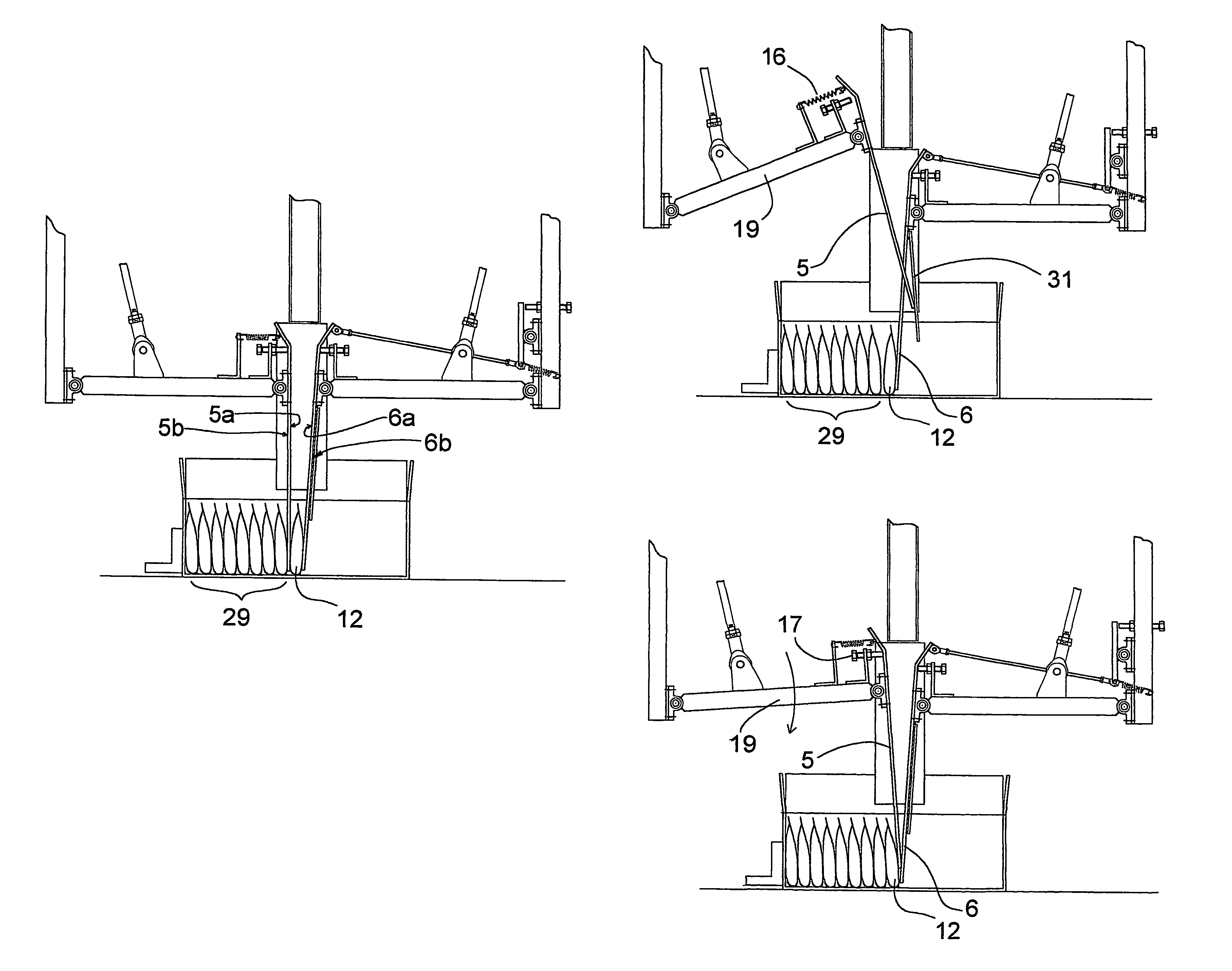
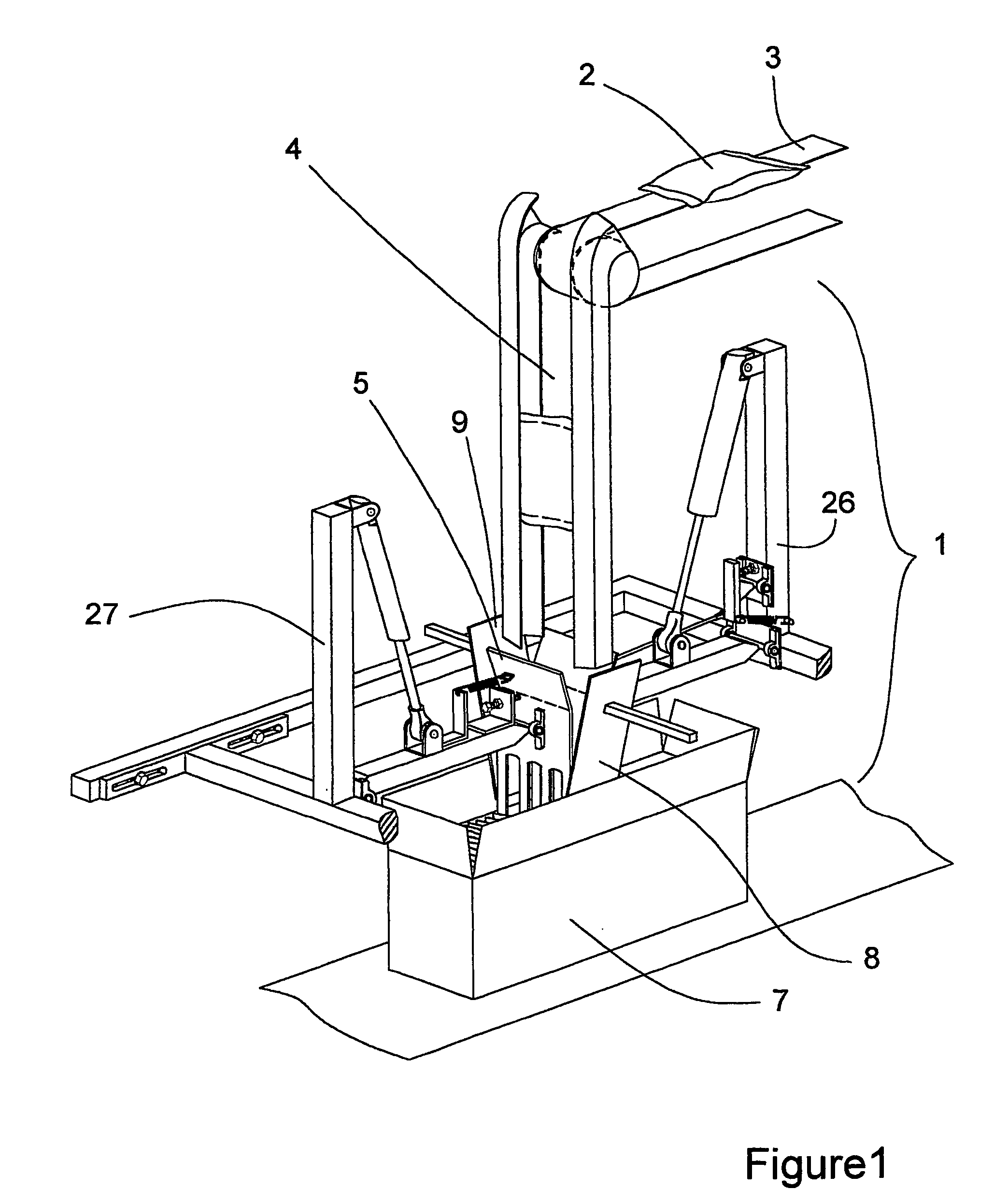
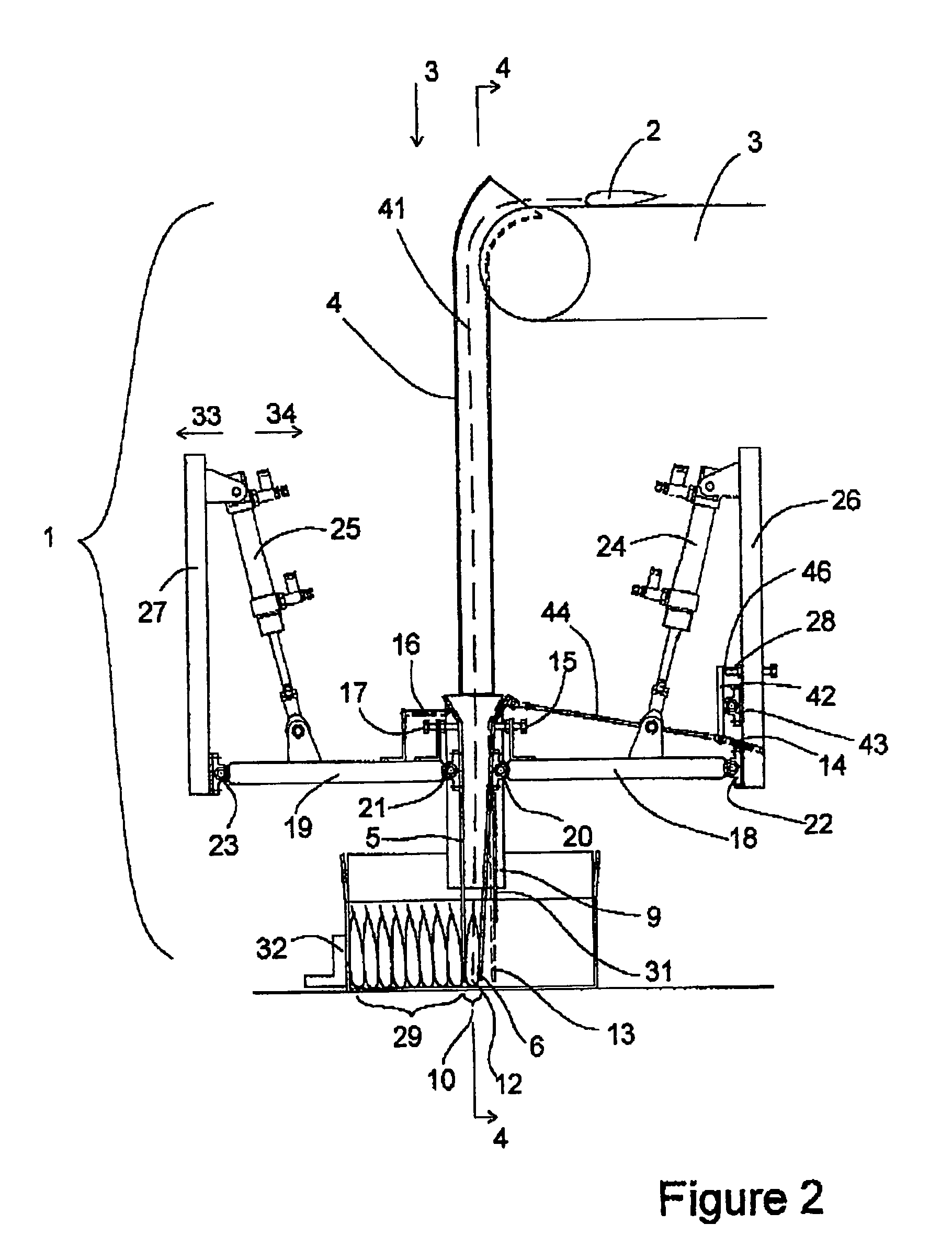
[0073]Referring to FIGS. 1, 2, 3 and 4, there is shown a device 1 for guiding flexible bags 2 from a conveyor 3 into a shipping container 7. A chute 4 is provided to guide the bags 2 from the conveyor 3 to the working elements of the device 1. The device consists essentially of a first moveable restraining member 5, having an anterior surface 5a and a posterior surface 5b and a second moveable restraining member 6, having an anterior surface 6a and a posterior surface 6b. The gap between the surfaces 5a and 6a defines a moveable cavity 10 into which the bags 2 are guided. A bag 12 is shown in FIG. 2 having been guided into position at the floor of the container 7.

[0074]The first and second restraining members 5, 6 are attached to mechanically operated sub-assemblies that actua...


PUM

PropertyMeasurementUnit
coefficient of frictionaaaaaaaaaa
gravityaaaaaaaaaa
forceaaaaaaaaaa

Abstract

A device for filling a container with a plurality of objects standing substantially upright on a floor portion of the container includes: a depositing cavity temporarily created and maintained in the container for receiving one of the plurality of objects; a first moveable planar restraining member having a first anterior surface facing the depositing cavity and a first posterior surface, the first posterior surface restraining a previously deposited object against movement; and a second moveable planar restraining member having a second anterior surface facing the depositing cavity and a second posterior surface. The first and second restraining members are operationally arranged to be removably insertable into and between the opposing side walls of the container. After one of the plurality of objects is deposited into the depositing cavity, the first restraining member is moveable from a position on a first side of one of the plurality of objects, and the second restraining member is moveable away from the first restraining member to create a new depositing cavity.

Description

FIELD OF THE INVENTION[0001]This invention relates to high-volume commercial packing processes and equipment. In particular, it relates to a device and procedure for sequentially guiding individual objects into a container.BACKGROUND TO THE INVENTION[0002]Many technologies exist for the packing of flexible packages, particularly bags or pouches, into containers. Some machines place or drop the packages flat in the container, others position the packages vertically within the container. Most of the machines available to place bags or pouches in a packing case with a vertical orientation tend to be large, expensive and capable of high speed operation.[0003]The trend in many areas of manufacturing including the food industry is for more frequent product changeovers with shorter production runs. A concurrent trend is to reduce the number of packages in a shipping container. There is also constant economic pressure to reduce the cost, size and complexity of equipment, improve the flexibi...

Claims


Application Information

Patent Timeline
Patent Type & Authority Patents(United States)
IPC IPC(8): B65B35/12B65B5/08B65B5/10
CPCB65B5/08B65B5/108B65B35/12
Inventor HOOPER, LEON
Owner MFG SOLUTIONS
Why Eureka
Try Eureka