
Treatment of photic disturbances in the eye

a photic disturbance and eye technology, applied in the field of eye lenses, can solve the problems of adversely affecting the quality of vision in the pseudophakic eye, unexpected optical problems, and degrade vision, and achieve the effect of reducing or eliminating incident light photic disturbances

Inactive Publication Date: 2007-05-15
CORONCO MINAS THEODORE
View PDF12 Cites 14 Cited by
  • Summary
  • Abstract
  • Description
  • Claims
  • Application Information

AI Technical Summary

Benefits of technology

"The invention relates to a method and apparatus for reducing photic disturbances in the eye caused by oblique light. The inventor has discovered that the refracted rays of obliquely incident light can degrade vision in the pseudophakic eye, and that the dimensions of the intraocular lens can allow such light to strike the nasal perimeter of the lens and be focused onto the nasal retina, causing photic disturbances. The invention proposes an ocular lens or intraocular lens that reduces or eliminates oblique light focusing on the interior of the eye, and a method for producing such lenses. The technical effect of the invention is to improve the quality of vision in patients with photic disturbances caused by oblique light."

Problems solved by technology

The inventors have found that refracted rays of obliquely instant light may degrade vision in the pseudophakic eye, with oblique or off-axis light from the temporal field posing unexpected optical problems after the crystalline lens has been replaced by an intraocular lens.
Such unwanted image formation can adversely impact the quality of vision in the pseudophakic eye.
Thus, prior art attempts to treat photic disturbances such as PDP have been unsatisfactory.

Method used


Image

  • Treatment of photic disturbances in the eye
  • Treatment of photic disturbances in the eye
  • Treatment of photic disturbances in the eye

Examples


example 1

Oblique Light Focusing and Pseudophakic Dysphotopsia

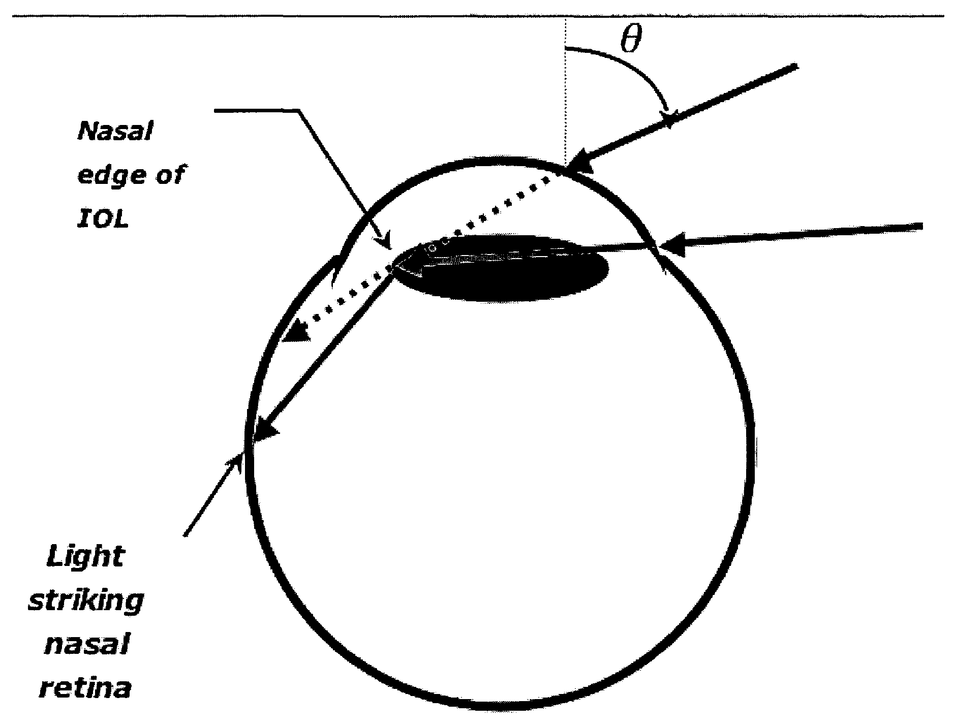
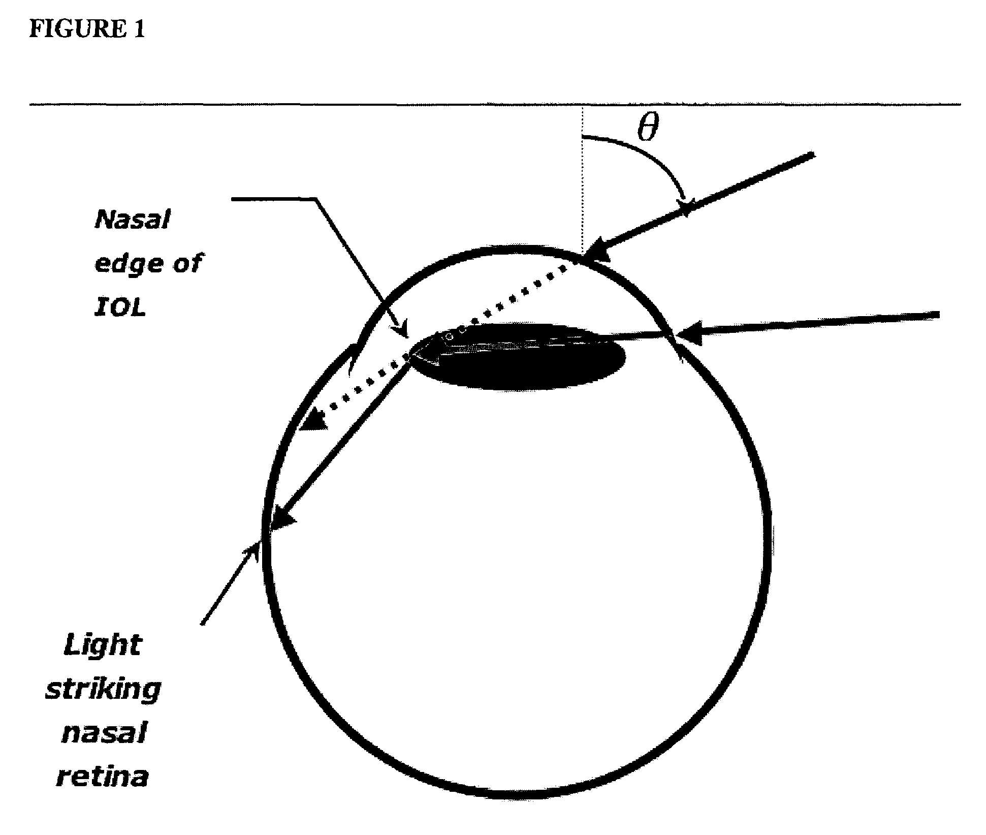
[0043]FIG. 1 shows oblique light striking an IOL at the nasal perimeter or edge and being focused into the eye striking nasal retina. Oblique light incident on the temporal limbus is concentrated at the nasal edge of the intraocular lens. Light rays continue forwards to strike the nasal retina at different areas depending on angle of incidence (⊖). FIG. 1 is based on the following experiments:

Clinical Observation

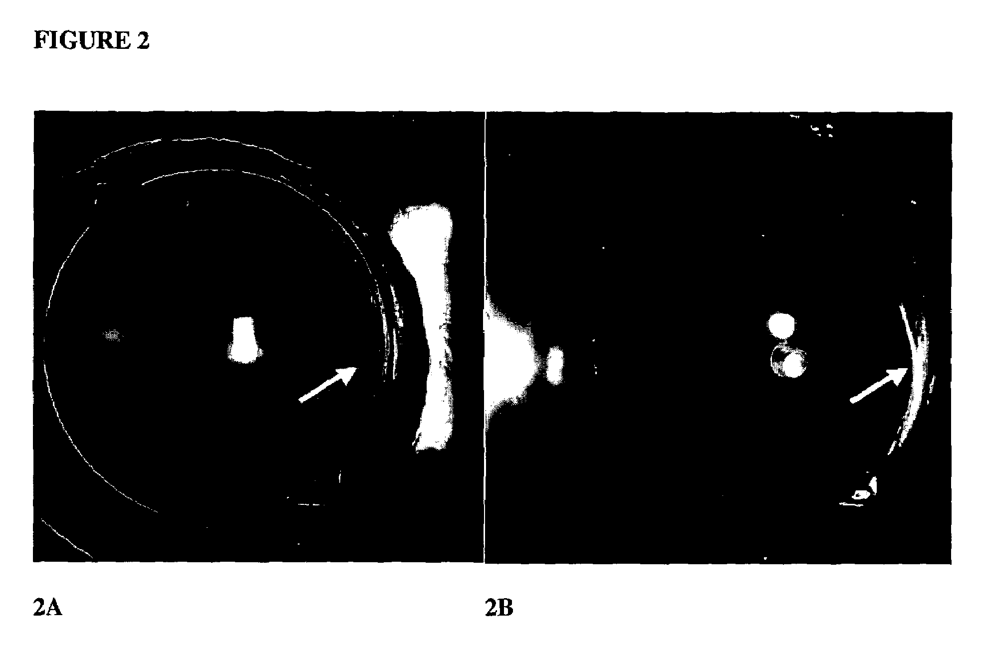
[0044]Using a hand held light source we have been able to induce PDP symptoms in 3 patients referred for second opinions who had developed PDP after having been implanted with square edged intraocular lenses. They described typical photic symptoms at the precise moment when a focus was formed at the nasal edge of their intraocular lens. FIG. 2 shows this focus formed with oblique incident light. FIG. 2A shows a square edged intraocular lens implanted in a 47-year old patient's right eye. Right: Off-axis light from the tempo...

example 2

Case Studies

[0049]This study indicated that depending on the angle of incidence, several secondary images are formed from oblique light. Our findings indicate that some of the images have low intensity and yet may be noticed in photopic conditions. However, under scotopic conditions, such secondary images may become particularly noticeable to the patient and disturb vision.

[0050]The oblique light focusing explanation of pseudophakic dysphotopsia in the pseudophakic eye was confirmed with three pseudophakic patients. Using a peripherally placed penlight to focus light onto the nasal aspect of the intraocular lens we were able to precisely reproduce symptoms of arcs of light in the temporal visual field, especially at night.

[0051]An illustration of this new explanation for pseudophakic dysphotopsia in the pseudophakic eye shown in FIGS. 6A–6C. Secondary images formed on the nasal retina by light bundles at angles of 65° (FIG. 6A), 85° (FIG. 6B) and 92° (FIG. 6C) incidence at the tempo...


PUM


Abstract

An ocular lens treated so that at least a portion of the lens perimeter diminishes peripheral light focus on the interior of the eye in use, so as to ameliorate phobic eye disturbances. The lens perimeter of intraocular lenses, artificial corneas and contact lenses are treated to diminish peripheral light focus.

Description

BACKGROUND OF THE INVENTION[0001]The present invention is directed to ocular lenses, including intraocular lenses, artificial corneas and contact lenses, treated so as to prevent photic disturbances in the eye.BACKGROUND OF THE INVENTION[0002]Cataract extraction and intraocular lens insertion may be regarded as one of the most successful human body part replacement procedures ever developed. It has been said that “cataract surgery, the most successful procedure in modern medicine, yields outcomes that are unsurpassed by any other surgical procedure” (Obstbaum S. A. “Effective cataract surgery—an undervalued procedure”, J Cataract Refract Surg. 1998;24: 1417).[0003]The deformable intracoular lens (IOL) was developed in the early 1980s. Formed of polymeric material, IOLs are sufficiently soft and flexible to allow the lens to be folded for insertion into the eye through an incision of reduced size.[0004]IOLs typically incorporate a disk-shaped, transparent lens optic and may include s...

Claims


Application Information

Patent Timeline
Patent Type & Authority Patents(United States)
IPC IPC(8): A61F2/16G02C7/04
CPCA61F2/1613
Inventor CORONCO, MINAS THEODORE
Owner CORONCO MINAS THEODORE
Learn More