Ink-jet head and producing method thereof

a technology of inkjet head and producing method, which is applied in the field of inkjet head, can solve the problems of reducing or failing deteriorating the piezoelectric actuator in particular, deformation of the actuator, etc., and achieves the effect of releasing or minimizing the ink squirting capability of the actuator

Active Publication Date: 2007-05-22
BROTHER KOGYO KK
View PDF9 Cites 0 Cited by
  • Summary
  • Abstract
  • Description
  • Claims
  • Application Information

AI Technical Summary

Benefits of technology

[0008]It is an object of the present invention to provide an ink-jet head that can release or minimize reduction of an ink squirting capability of the actuator by preventing adhesion of ink, a sealing member and the like to the actuator, and a producing method thereof.
[0010]In the construction mentioned above, the protrusion is presented at one side of the driving portion serving as the actuator. While a construction having no protrusion can allow an easy entry of the ink into the head from the other side, the construction of the invention having the protrusion can prevent the entry of the ink into the head by the protrusion. Thus, the construction of the invention can prevent the adhering of the ink to the actuator, thus releasing or minimizing the problem of reduction of the ink squirting capability of the actuator. Further, when the sealing member is employed as in the existing technique mentioned above, since the sealing member is prevented from adhering to the actuator by the protrusion, the problem of reduction of the ink squirting capability of the actuator can be even more released.
[0012]In the construction mentioned above, the actuator unit is bonded to the passage unit, and the reservoir unit is bonded to the passage unit so that the reservoir unit is extended to bridge over the actuator unit and spaced apart therefrom. This construction including the protrusion provided in said area can also provide the same effect as in the first aspect of the invention.
[0014]The front end of the first protrusion is equivalent to the bonded surface of the second aspect of the invention. By forming both the first protrusion and the second protrusion as the protrusion in the first and second aspects of the invention by half-etching, manufacturing costs can be reduced.

Problems solved by technology

Although there are presented a variety of actuators, including those as mentioned above, the existing actuators all suffer from the problem that when the ink adheres to the actuator, the ink squirting capability of the actuators reduces or fails.
However, according to this technique, although the adhering of the ink to the actuator can be prevented, there is a possibility that the sealing member may enter into the head to cause adherence of the sealing member to the actuator.
When the sealing member adheres to the actuator, the deformation of the actuator, the piezoelectric actuator in particular, is deteriorated.
Therefore, the existing techniques mentioned above are unsatisfactory for solving the problem of reduction of the ink squirting capability of the actuator.

Method used


Image

  • Ink-jet head and producing method thereof
  • Ink-jet head and producing method thereof
  • Ink-jet head and producing method thereof

Examples


Embodiment Construction

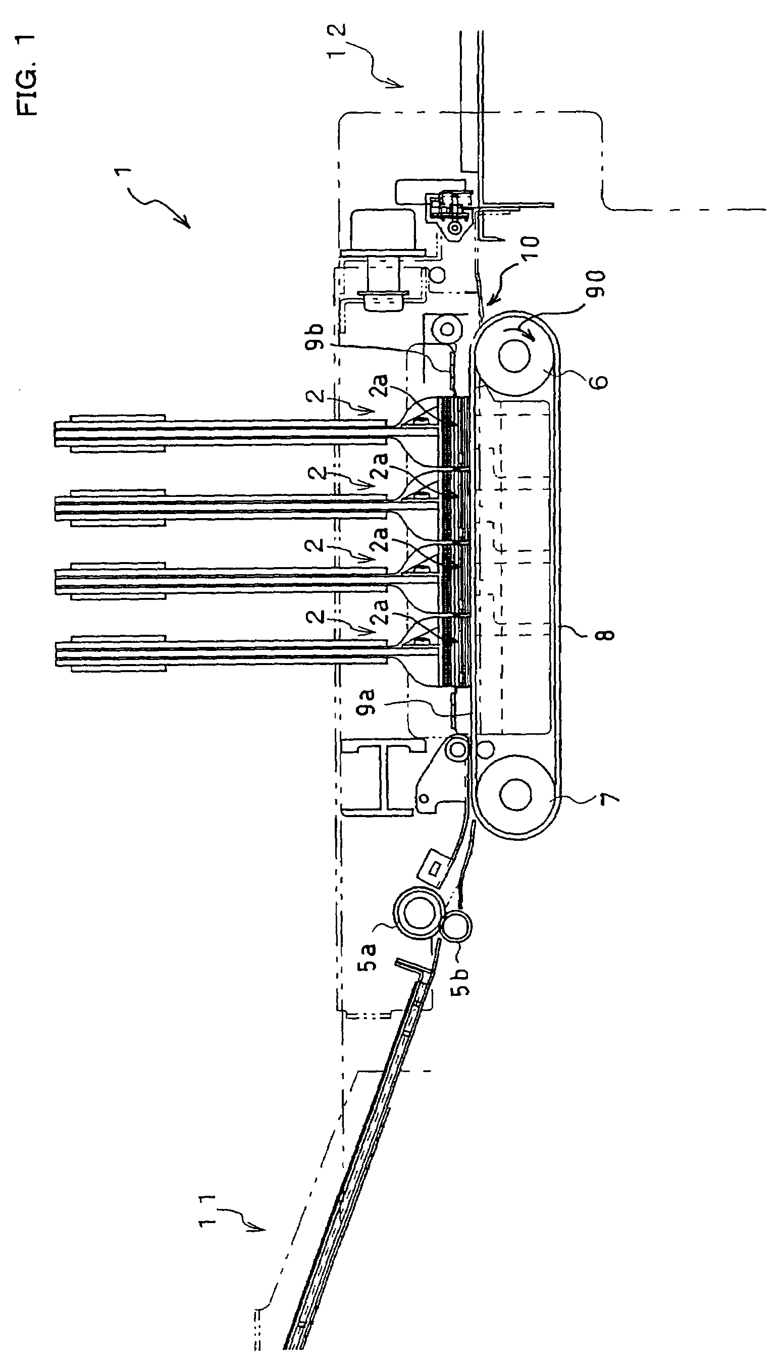
[0027]FIG. 1 is an entire construction diagram showing an example of a printer including an ink-jet head according to an embodiment of the present invention. The ink-jet printer 1 of this embodiment is a color ink-jet printer having four ink-jet heads 2. The ink-jet printer 1 has a paper feed portion 11 (left side when viewed in the illustration) and a paper discharge portion 12 (right side when viewed in the illustration). It also has in an interior thereof a paper carrier passage running from the paper feed portion 11 toward the paper discharge portion 12.

[0028]A pair of paper feed rollers 5a, 5b are disposed on the directly downstream side of the paper feed portion 11, to feed the paper of the recording medium from the left to right when viewed in the illustration. Two belt rollers 6, 7 and a loop carrier belt 8 extended between the both rollers 6, 7 are disposed in an intermediate portion of the paper carrier passage.

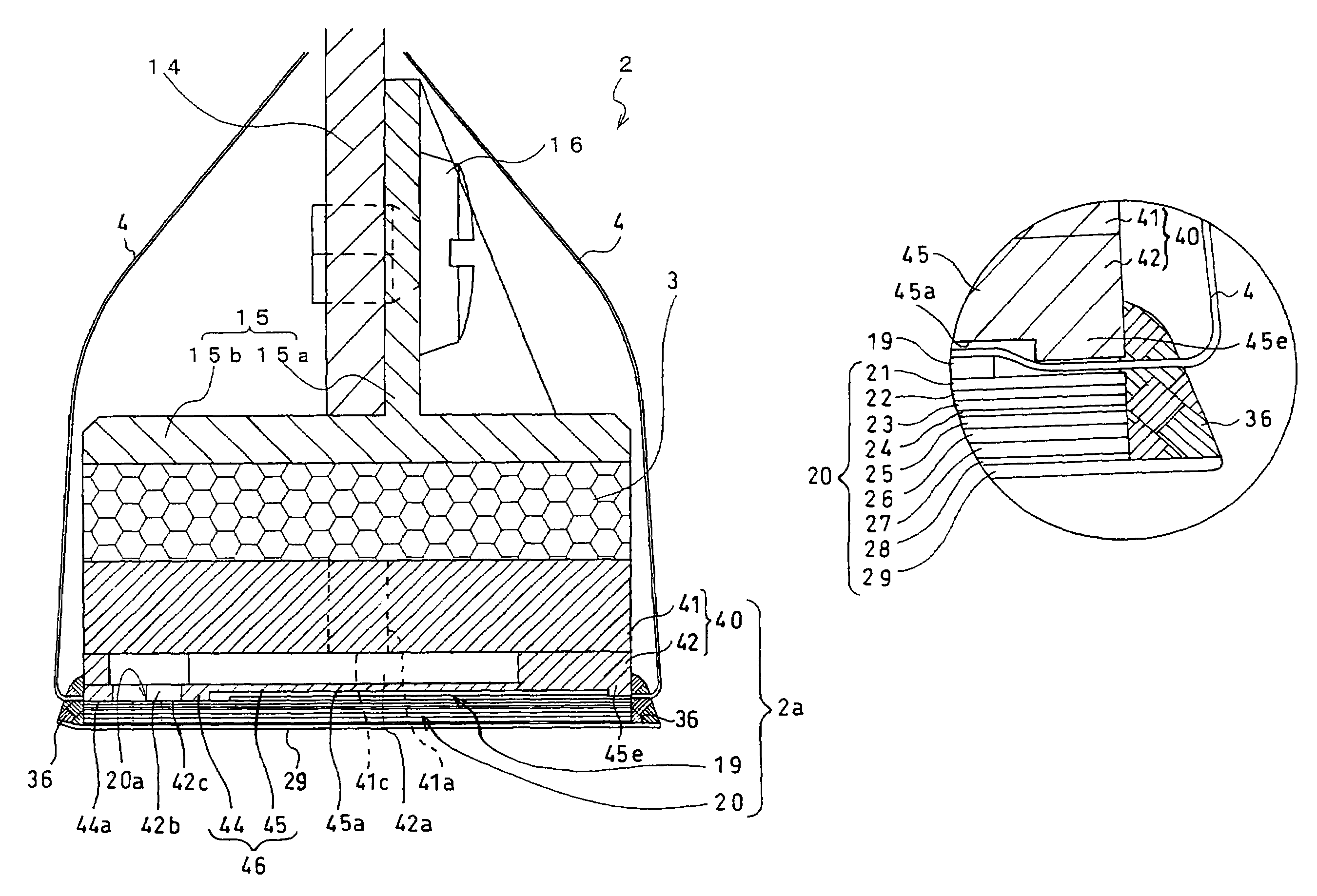
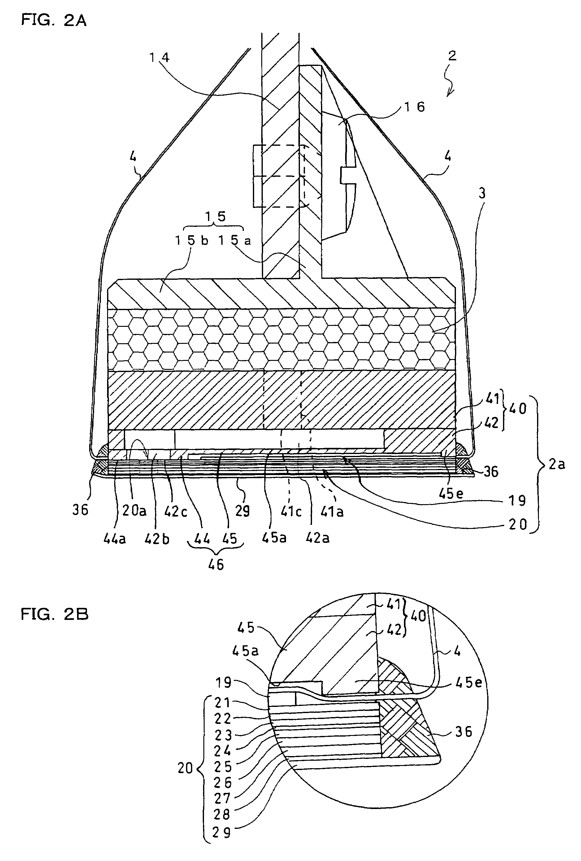
[0029]The carrier belt 8 has a two-layer structure comprising ...


PUM


Abstract

An ink-jet head is formed by laminating a passage unit including a plurality of individual ink passages running to a nozzle through a pressure chamber and a reservoir unit including an ink reservoir in which ink is stored and from which the stored ink is fed to the passage unit. The reservoir unit has a bonded portion bonded to the passage unit and a spaced portion spaced apart from and opposite to the passage unit which are formed on a bottom thereof. The spaced portion has a protrusion formed at an end thereof opposite to the bonded portion to protrude in a direction of the passage unit. FPC is drawn out from an opening between the protrusion and the passage unit and an adhesive is applied to this opening.

Description

BACKGROUND OF THE INVENTION[0001]1. Field of the Invention[0002]The present invention relates to an ink-jet head for squirting ink at recording medium for recording a formed image and the like.[0003]2. Description of the Related Art[0004]In the ink-jet head, ink from an ink tank is supplied to a pressure chamber through a common ink chamber, to impart squirting energy to the ink in the pressure chamber and then the energized ink is squirted from a nozzle. The head is provided with an actuator for imparting the squirting energy to the ink in the pressure chamber. The actuator is electrically connected to a flexible printed circuit (FPC). The actuator is driven under driving signal fed from a driver IC through the FPC.[0005]A variety of actuators are in use, including a piezoelectric actuator and a capacitance type actuator. In the piezoelectric actuator, the actuator is disposed opposite to the pressure plate to form a partition wall of the pressure chamber, so that when the actuator...

Claims


Application Information

Patent Timeline
Patent Type & Authority Patents(United States)
IPC IPC(8): B41J2/14B41J2/045B41J2/055B41J2/16
CPCB41J2/14209B41J2/1609B41J2/1623B41J2/1626B41J2/1631B41J2002/14217B41J2002/14225B41J2002/14306B41J2002/14459B41J2002/14491B41J2202/20
Inventor TAIRA, HIROSHI
Owner BROTHER KOGYO KK
Why Eureka
Try Eureka