Miniaturization facilitating plug connectors

a technology of plug connectors and connectors, applied in the direction of contact members penetrating/cutting insulation/cable strands, coupling device connections, electrical apparatus, etc., can solve the problems of inconvenient and inefficient arrangement of coaxial cables, difficult winding or twisting, and difficult to arrange in a narrow space. , to achieve the effect of preventing the wicking of coaxial cables and avoiding undesirable wire hardening

Inactive Publication Date: 2007-05-22
MOLEX INC
View PDF19 Cites 20 Cited by
  • Summary
  • Abstract
  • Description
  • Claims
  • Application Information

AI Technical Summary

Benefits of technology

[0006]Problems such as those noted above are addressed with advantageous results by the present invention, which has been made in view of the above circumstances. In this regard, it is an object of the present invention to provide a technique with which, in mounting coaxial cables to a connector, solder wicking to the coaxial cables is prevented thereby avoiding undesirable hardening of wires which are components of the coaxial cables, which is especially important for connectors that are ever increasingly miniaturized.
[0009]When the cable holders are fitted into the fitting holes via the through holes, the backbone portions of the respective cable holders are positioned in the through holes. Comparing this configuration with the prior approach where the cable holders are fitted into the fitting holes in the housing and then the housing is covered with the shell, where both the present invention and the prior approach are same in the length of the cable holders and in the amount of insertion to the fitting holes in the housing, the cable holders of the present invention can reduce the height of the connector by an amount of the backbone portion facing to the through holes in the shell.
[0010]According to an overall aspect or object of the present invention, the wires of an electrical connector can be prevented from hardening and the connector can be miniaturized. The invention finds special applications in plug connectors for miniaturized electronic equipment.

Problems solved by technology

Once the outer conductor 308 becomes hard, the coaxial cables are not flexible, and they thereby become difficult to wind or twist and / or difficult to arrange in a narrow space such as inside a portable telephone.
Such difficulties make the coaxial cables inconvenient and inefficient and at times unsuitable for applications where increased miniaturization is an objective.
Further, if extraordinary outer forces are imparted to the hardened portion, cracking of the hardened portion may be experienced.
When the hardening phenomenon due to soldering occurs at such hinge portion cable areas, a device such as a portable telephone becomes difficult to fold, the connector is not easily passed through a cable insertion-hole (not shown) at the hinge, and / or connection failure may be induced.
Meanwhile, the need for miniaturization of portable instruments has been increasing over the years, which means that the outer dimensions of connectors cannot be increased.

Method used


Image

  • Miniaturization facilitating plug connectors
  • Miniaturization facilitating plug connectors
  • Miniaturization facilitating plug connectors

Examples


Embodiment Construction

[0051]As required, detailed embodiments of the present invention are disclosed herein; however, it is to be understood that the disclosed embodiments are merely exemplary of the invention, which may be embodied in various forms. Therefore, specific details disclosed herein are not to be interpreted as limiting, but merely as a basis for the claims and as a representative basis for teaching one skilled in the art to variously employ the present invention in virtually any appropriate manner.

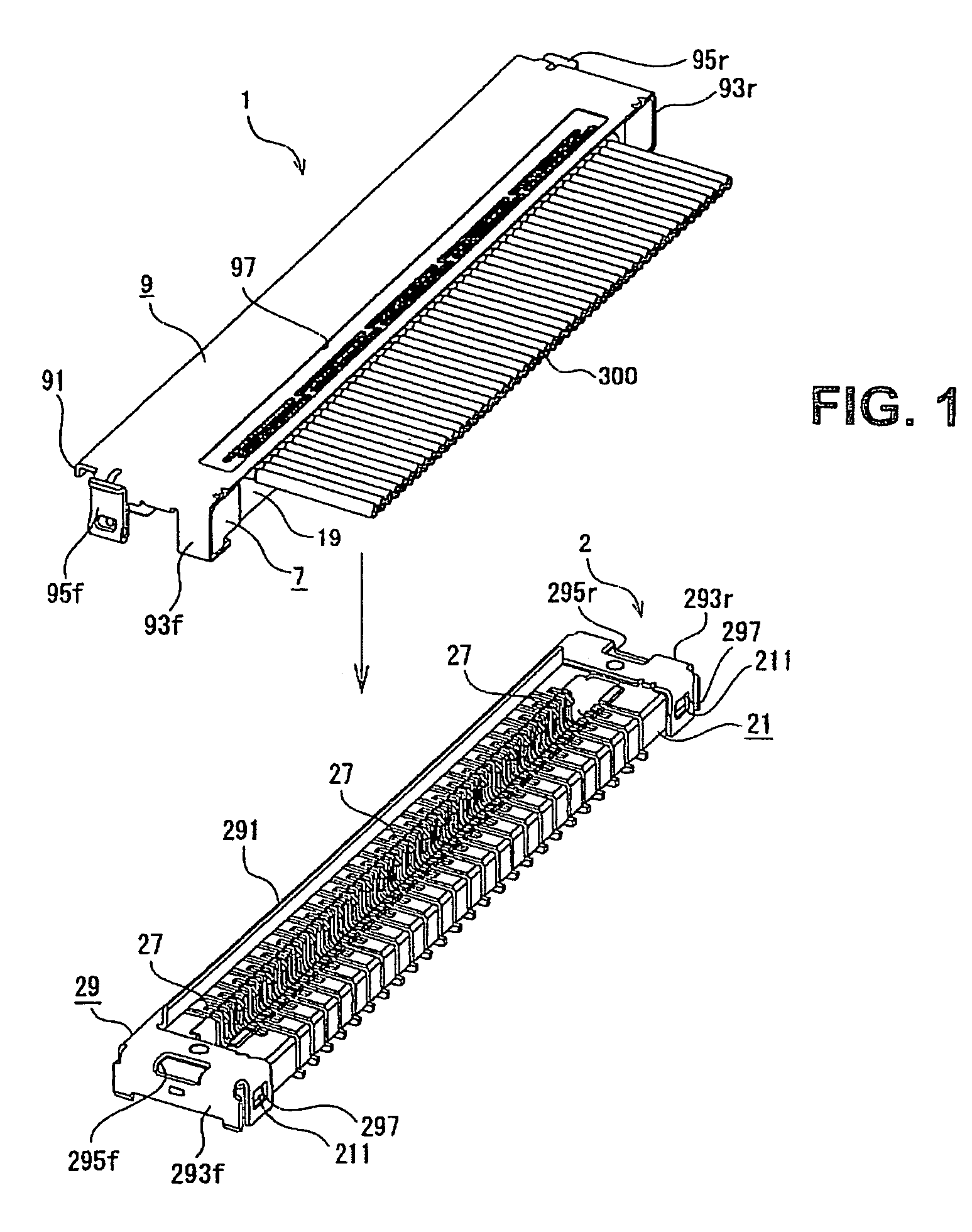
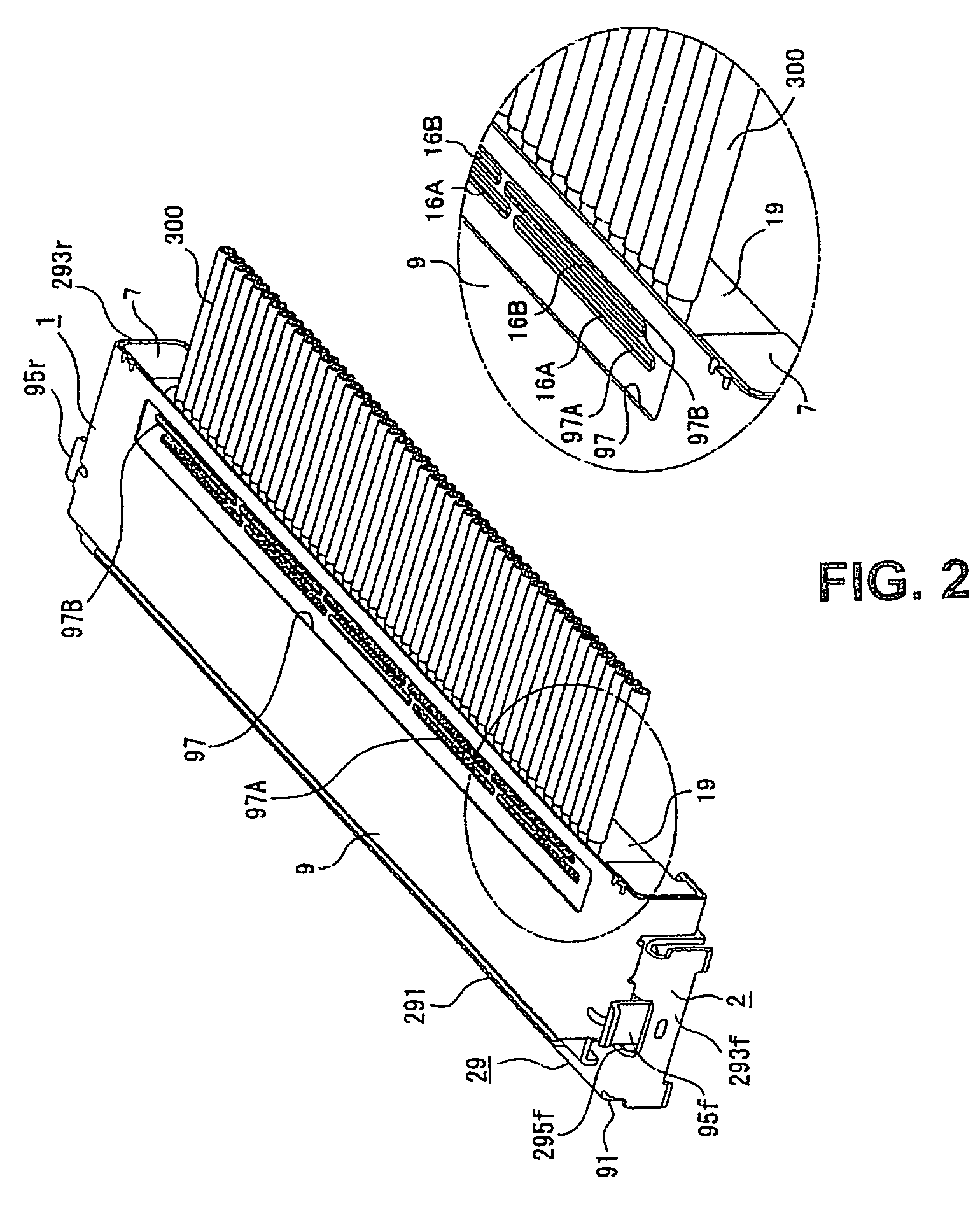
[0052]FIG. 1 is a perspective view illustrating, together with a mating connector 2, a connector 1 according to the present invention in a state prior to its mounting to the mating connector 2. The illustrated connector is a plug connector. Further, FIG. 2 is a perspective view of the connector 1 as mated with the mating connector 2. It is to be noted that, although not shown in FIG. 2, the connector 1 is also attached to the other end portion of a coaxial cable 300 for mounting to the mating conne...


PUM


Abstract

Connectors to which cables are attached are provided. Included is a cable having a conductor covered with an insulator, the connector comprising a housing and a terminal held in the housing and connected to the conductor. Cable holders are arranged in the housing and hold a distal end portion of the cable. A shell is fitted in the housing to cover these members. The cable holders hold the cable in the housing, the housing including: fitting holes for fitting the cable holders, the shell including: through holes provided in a position opposed to the fitting holes, the cable holders having a double-legged or double-tined portion consisting of a pair of legs or tines for grasping the cables, such as by pinching or nipping, and a board portion or backbone for connecting the legs or tines together. The cable holders straddle and pinch the cable while the board portion is positioned in the through holes when fitted in the fitting holes via the through holes, thereby reducing size. Another advantage is preventing solder hardening of the wires, thereby further facilitating miniaturization.

Description

BACKGROUND OF THE INVENTION[0001]The present invention relates to a connector for a plurality of cables. The connector provides electrical connection between the cables and a circuit board in a manner that fosters miniaturization and avoids undue stiffness of the cables at the connector.[0002]Coaxial cables are known as cables for transmitting high-frequency signals in portable telephones, personal computers, and the like in order to transmit a volume of information. As shown in prior art FIGS. 37 and 38, a typical coaxial cable 300 is composed of a signal line 306 having a centrally located inner conductor 302 covered with an inner insulator 304, an outer conductor 308 consisting of a large number of spirally wound or braided electric wires and covering the signal line 306, and an outer insulator 310 covering the outer conductor 308.[0003]Soldering methods are among the technologies available to connect a cable such as the coaxial cable 300 to a connector. As shown in FIG. 39, a kn...

Claims


Application Information

Patent Timeline
Patent Type & Authority Patents(United States)
IPC IPC(8): H01R9/05
CPCH01R9/0527H01R12/592H01R12/775H01R12/598H01R12/777H01R31/085
Inventor MIYAZAKI, TATSUYA
Owner MOLEX INC
Why Eureka
Try Eureka