AI technical title is built by Patsnap AI team. It summarizes the technical point description of the patent document.
a tubal occlusion and tube technology, applied in the field of tubal occlusion methods and devices, can solve the problems of time-consuming technique, increased and repeated application of anesthesia, so as to reduce the risk of bowel injury and eliminate the risk of ectopic pregnancy
Inactive Publication Date: 2007-05-22
CYTYC CORP
View PDF51 Cites 51 Cited by
Summary
Abstract
Description
Claims
Application Information
AI Technical Summary
This helps you quickly interpret patents by identifying the three key elements:
Problems solved by technology
Method used
Benefits of technology
Benefits of technology
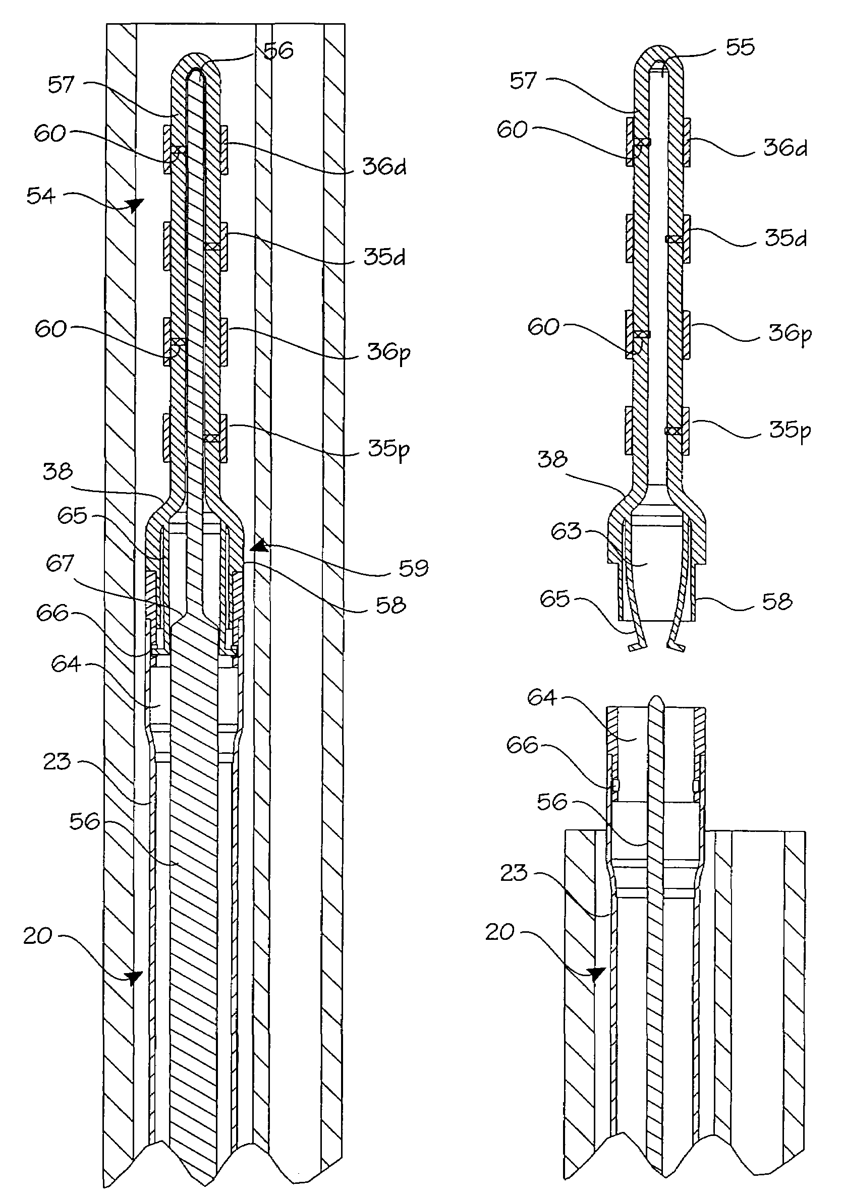
[0010]The method of the present invention provides a technique of sterilization, discussed in greater detail below, which involves the collapsing of the uterotubal junction and / or fallopian tube around a plug to create total occlusion of the tube. Total occlusion of the tube prevents male sperm from fertilizing female eggs, thus preventing conception.
[0013]The fact that the tissue destruction is performed outside the fallopian tubes, close to the uterine cavity in the thick portion of the uterotubal junction substantially reduces the risk of bowel injury. Advancement of any device beyond the isthmus of the fallopian tubes or within the fallopian tubes is not necessary, although in some cases insertion into the proximal portion of the fallopian tubes will be accomplished. No caustic substances come into contact with the peritoneum, obviating unpleasant side effects, and total occlusion of the lumen virtually eliminates the risk of ectopic pregnancy. Furthermore, no special technique is required to perform the procedure.
Problems solved by technology
Aside from permanent scar formation at the site of incision, there are reported cases of death due to anesthesia complications.
Major drawbacks from this procedure are the need of repeat applications and a significant level of side effects.
This technique is time consuming, however, and requires a high level of technical skill both for the preparation of the silicone and for performing the procedure.
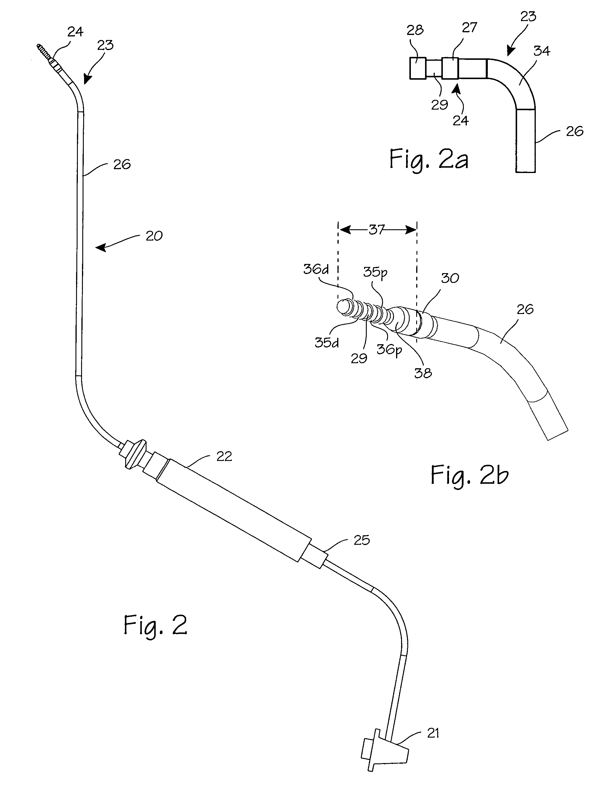
The electrode is advanced into the fallopian tube and energized to thermally damage the fallopian tube, thereby causing enough scarring of the fallopian tube to permanently occlude it.
However, the fallopian tubes have proven to be very difficult to cross with any useful device.
In the typical human anatomy, catheters and guidewires cannot always navigate through the fallopian tubes as required by the methods of the prior art.
The fact that the tissue destruction is performed outside the fallopian tubes, close to the uterine cavity in the thick portion of the uterotubal junction substantially reduces the risk of bowel injury.
Method used
Image
Click on the blue label to locate the original text in one second.
Reading with bidirectional positioning of images and text.
Examples
Embodiment Construction
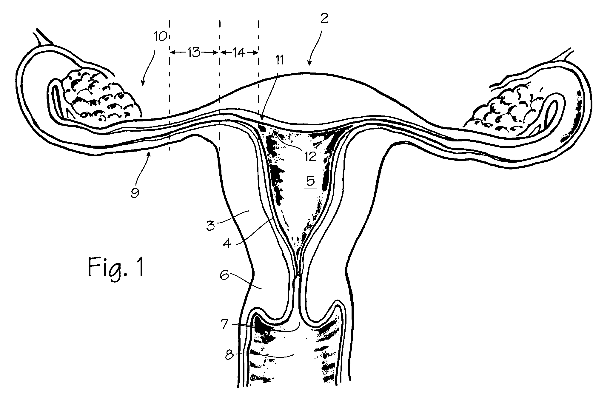
[0027]FIG. 1 shows some of the major elements of the female reproductive system. The uterus 2 is an organ of the female pelvis that has the shape of a pear. It consists of a thick muscular coat, the myometrium 3, a cavity having an inner mucosal lining of variable thickness called the endometrium 4, and a cavity referred to as the uterine cavity 5. The cervix 6 defines the cervical canal 7 which is an inferior opening to the vagina 8. The fallopian tube 9 is a hollow organ that connects the uterus to the ovary 10. The ovary is the organ that produces one or more eggs during every cycle of a woman's reproductive life. In the human female reproductive system, there is one uterus, two fallopian tubes and two ovaries (under normal conditions). The site where the fallopian tube and uterus connect is called the uterotubal junction 11. It is a section of tubular shape of about 10 mm in length. Its inner diameter in the resting position is less than 1 mm, but when gas or liquid is pushed th...
PUM
Abstract
A device for sterilizing females by occluding the uterotubal junction. The device includes a catheter with a releasable heat generating plug which is used to thermally damage the uterotubal junction and cause it to constrict around the plug, after which the plug is released from the catheter and left in place in the uterotubal junction.
Description
[0001]This application is a continuation of U.S. application Ser. No. 10 / 075,854 filed Feb. 12, 2002, now U.S. Pat. No. 6,726,682, which is a continuation U.S. application Ser. No. 09 / 579,976 filed May 26, 2000, now U.S. Pat. No. 6,346,102, which is a continuation of U.S. application Ser. No. 09 / 372,394 filed Aug. 10, 1999, now U.S. Pat. No. 6,068,626, which is a continuation of U.S. application Ser. No. 09 / 063,119 filed Apr. 20, 1998, now U.S. Pat. No. 5,954,715, which is a continuation-in-part of U.S. provisional patent applications 60 / 048,632 filed Jun. 5, 1997 and 60 / 054,388 filed Jul. 31, 1997.FIELD OF THE INVENTIONS [0002]The present invention relates to an apparatus and method for permanently closing body vessels such as veins, arteries, body tubes, etc. The present invention particularly, though not exclusively, relates to the occlusion of the female mammalian fallopian tubes. In particular, this invention is directed to a relatively simple surgical procedure for sterilizing...
Claims
Application Information
Patent Timeline
Application Date:The date an application was filed.
Publication Date:The date a patent or application was officially published.
First Publication Date:The earliest publication date of a patent with the same application number.
Issue Date:Publication date of the patent grant document.
PCT Entry Date:The Entry date of PCT National Phase.
Estimated Expiry Date:The statutory expiry date of a patent right according to the Patent Law, and it is the longest term of protection that the patent right can achieve without the termination of the patent right due to other reasons(Term extension factor has been taken into account ).
Invalid Date:Actual expiry date is based on effective date or publication date of legal transaction data of invalid patent.

