
Processes for treating halogen-containing gases

a technology for halogen-containing gas and process, which is applied in the direction of chemistry apparatus and processes, separation processes, dispersed particle separation, etc., can solve the problems of halogen-containing gas environmental hazards, inability to efficiently remove effluent streams from effluent, and especially problematic treatment of fluorine gas (fsub>2/sub>), so as to reduce or eliminate the amount of halogen-containing gas released

Inactive Publication Date: 2007-05-22
BATTELLE MEMORIAL INST
View PDF25 Cites 7 Cited by
  • Summary
  • Abstract
  • Description
  • Claims
  • Application Information

AI Technical Summary

Benefits of technology

[0009]Halogen-containing gases are commonly-occurring emissions from manufacturing or cleaning processes such as etching in semiconductor manufacturing or metal cleaning in automobile manufacturing. Fluorine-laden gases are also a major byproduct from aluminum smelting. The disclosed processes and apparatuses offer an efficient abatement option for substantially decreasing or eliminating the amount of halogen-containing gas released into the atmosphere by industry.

Problems solved by technology

Halogen-containing gases are environmental hazards and must be removed or reduced from emission sources.
Treatment of fluorine gas (F2) is especially problematic since it is only marginally soluble in water and, thus, cannot be efficiently removed from an effluent stream via water scrubbing.
The solubility in water is also poor for other halogen-containing gases such as trichloroethylene, chloroform, perchloroethylene, various chlorofluorocarbons (“CFCs”), and various perfluorinated carbons (“PFCs”).
In addition to the high heat requirements and the need for a fuel gas, the conventional treatment method suffers from corrosion problems since the formed HF is highly corrosive at such high temperatures.

Method used


Image

  • Processes for treating halogen-containing gases
  • Processes for treating halogen-containing gases
  • Processes for treating halogen-containing gases

Examples


example 1

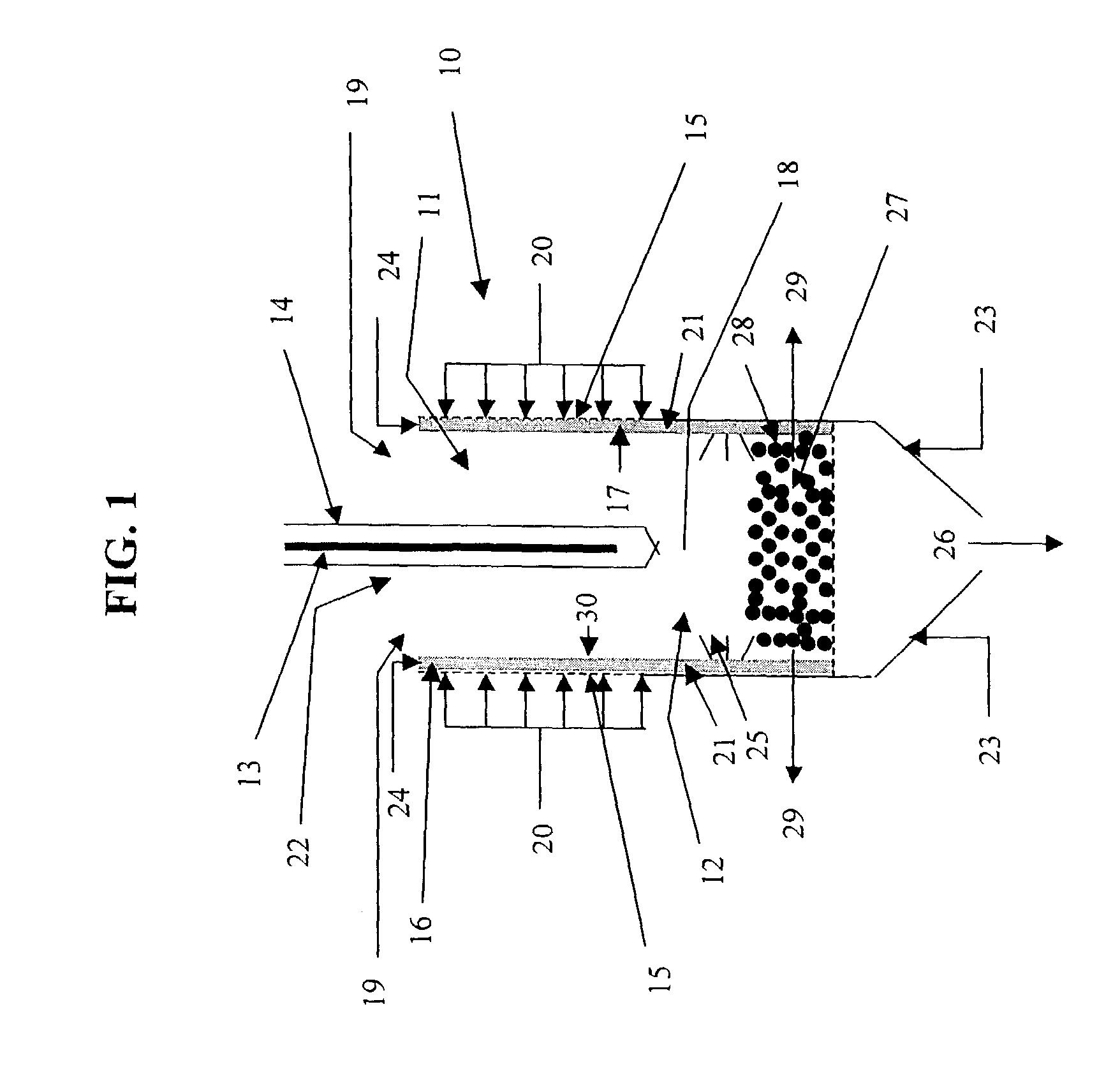
[0120]A treatment gas containing 1000 ppm F2 in N2 background gas was mixed with various H2 streams (at a 1:1 H2:F2 molar ratio and a 2:1 H2:F2 molar ratio). The treatment gas and H2 were supplied at ambient temperature and pressure. The resulting feed gas mixtures were introduced into the annular gap of a silent discharge plasma reactor having a configuration as shown in FIG. 4. A non-thermal plasma was generated in the feed gas mixtures with AC voltages having different frequencies applied to the high voltage electrode (400 Hz, 200 Hz and 100 Hz). The reactor temperature ranged from 30-35° C. The resulting amount of F2 in the exhaust gas stream and energy required is shown in the graph of FIG. 6.

example 2

[0121]Treatment gases containing 4000, 2000, or 1000 ppm F2 in N2 background gas were mixed an H2 stream at a 2:1 H2:F2 molar ratio. The treatment gas and H2 were supplied at ambient temperature and pressure. The resulting feed gas mixtures were introduced into the annular gap of a silent discharge plasma reactor having a configuration as shown in FIG. 4. A non-thermal plasma was generated in the feed gas mixtures with a 200 Hz AC voltage applied to the high voltage electrode. The reactor temperature ranged from 30-35° C. The resulting amount of F2 in the exhaust gas stream and energy required is shown in the graph of FIG. 7.


PUM

PropertyMeasurementUnit
temperatureaaaaaaaaaa
temperaturesaaaaaaaaaa
temperatureaaaaaaaaaa

Abstract

There are disclosed various processes, apparatuses and systems for treating a halogen-containing gas such as F2 that involve generating a plasma in order to reduce chemically the halogen-containing gas into products that are more environmentally manageable. According to a particular embodiment, a reducing agent is mixed with the halogen-containing gas to produce a feed gas mixture and a non-thermal plasma is generated in the feed gas mixture in the presence of liquid water. According to another embodiment, a vaporized portion of a liquid reducing agent is mixed with the halogen-containing gas to produce a reaction mixture and a non-thermal plasma is generated in the reaction gas mixture to reduce the halogen-containing gas.

Description

PRIORITY CLAIM[0001]This application is a continuation-in-part of pending U.S. application Ser. No. 09 / 905,654, which has been assigned a filing date of Jul. 11, 2001 now U.S. Pat. No. 6,962,679.FIELD OF THE DISCLOSURE[0002]The present disclosure relates to processes and apparatuses for treating halogen-containing gas, particularly fluorine gas.BACKGROUND[0003]Halogen-containing gases are environmental hazards and must be removed or reduced from emission sources. Treatment of fluorine gas (F2) is especially problematic since it is only marginally soluble in water and, thus, cannot be efficiently removed from an effluent stream via water scrubbing. The solubility in water is also poor for other halogen-containing gases such as trichloroethylene, chloroform, perchloroethylene, various chlorofluorocarbons (“CFCs”), and various perfluorinated carbons (“PFCs”). Effluent streams from semiconductor manufacturing often contain such halogen-containing gases. F2 is of particular interest sinc...

Claims


Application Information

Patent Timeline
Patent Type & Authority Patents(United States)
IPC IPC(8): B01D53/50B01D53/32B01D53/68B01D53/70B01D53/79C10L
CPCB01D53/32B01D53/68B01D53/70B01D53/79B01D2259/818
Inventor AARDAHL, CHRISTOPHER L.ORTH, RICK J.RAPPE, KENNETH G.LESSOR, DELBERT L.JOSEPHSON, GARY B.
Owner BATTELLE MEMORIAL INST
Learn More