
Method for determining number of dynamically temperature-adjusted power supply units needed to supply power according to measure operating temperature of power supply units

a technology of power supply unit and power supply unit, which is applied in the direction of liquid/fluent solid measurement, dc source parallel operation, instruments, etc., can solve the problems of uninterruptible power supply implementation using rechargeable batteries, loss of dc power, and requirement for redundant dc-dc conversion devices

Active Publication Date: 2007-05-22
HEWLETT-PACKARD ENTERPRISE DEV LP +1
View PDF17 Cites 40 Cited by
  • Summary
  • Abstract
  • Description
  • Claims
  • Application Information

AI Technical Summary

Benefits of technology

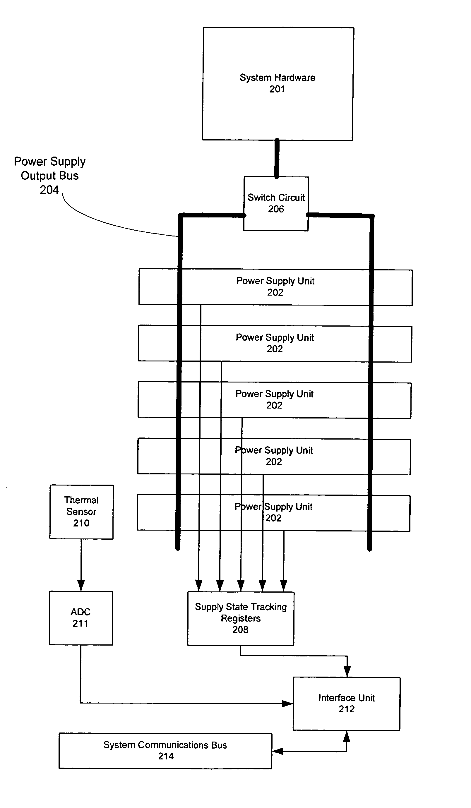
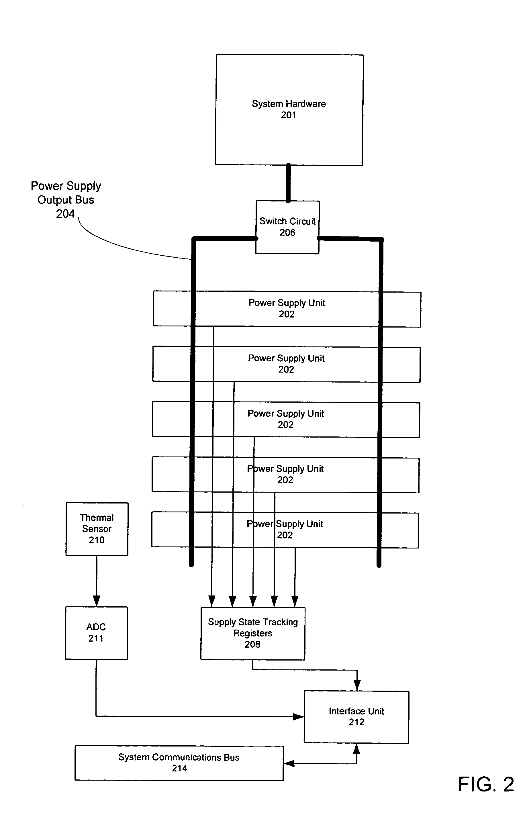
The invention provides a method and apparatus for providing dynamic temperature-adjusted power redundancy to a system. This involves tracking the number of power supply units that are currently in an up state and measuring the temperature at which they are operating. Using this information, logic circuitry calculates a temperature-adjusted number of power supply units that are currently needed to supply power to the system. This allows for a dynamic adjustment of power supply units based on temperature, ensuring a reliable and efficient system.

Problems solved by technology

Typically, a loss of DC power is caused by a loss of AC power to the AC-to-DC power supplies, or a failure of an AC-to-DC power supply.
Uninterruptible AC power supplies address the problem of AC power loss by providing a constant supply of AC power to AC-to-DC power supplies.
Typically, uninterruptible power supplies are implemented using rechargeable batteries, and in some cases, generators.
In many cases, these DC-DC conversion devices are also required to be redundant.

Method used


Image

  • Method for determining number of dynamically temperature-adjusted power supply units needed to supply power according to measure operating temperature of power supply units
  • Method for determining number of dynamically temperature-adjusted power supply units needed to supply power according to measure operating temperature of power supply units
  • Method for determining number of dynamically temperature-adjusted power supply units needed to supply power according to measure operating temperature of power supply units

Examples


Embodiment Construction

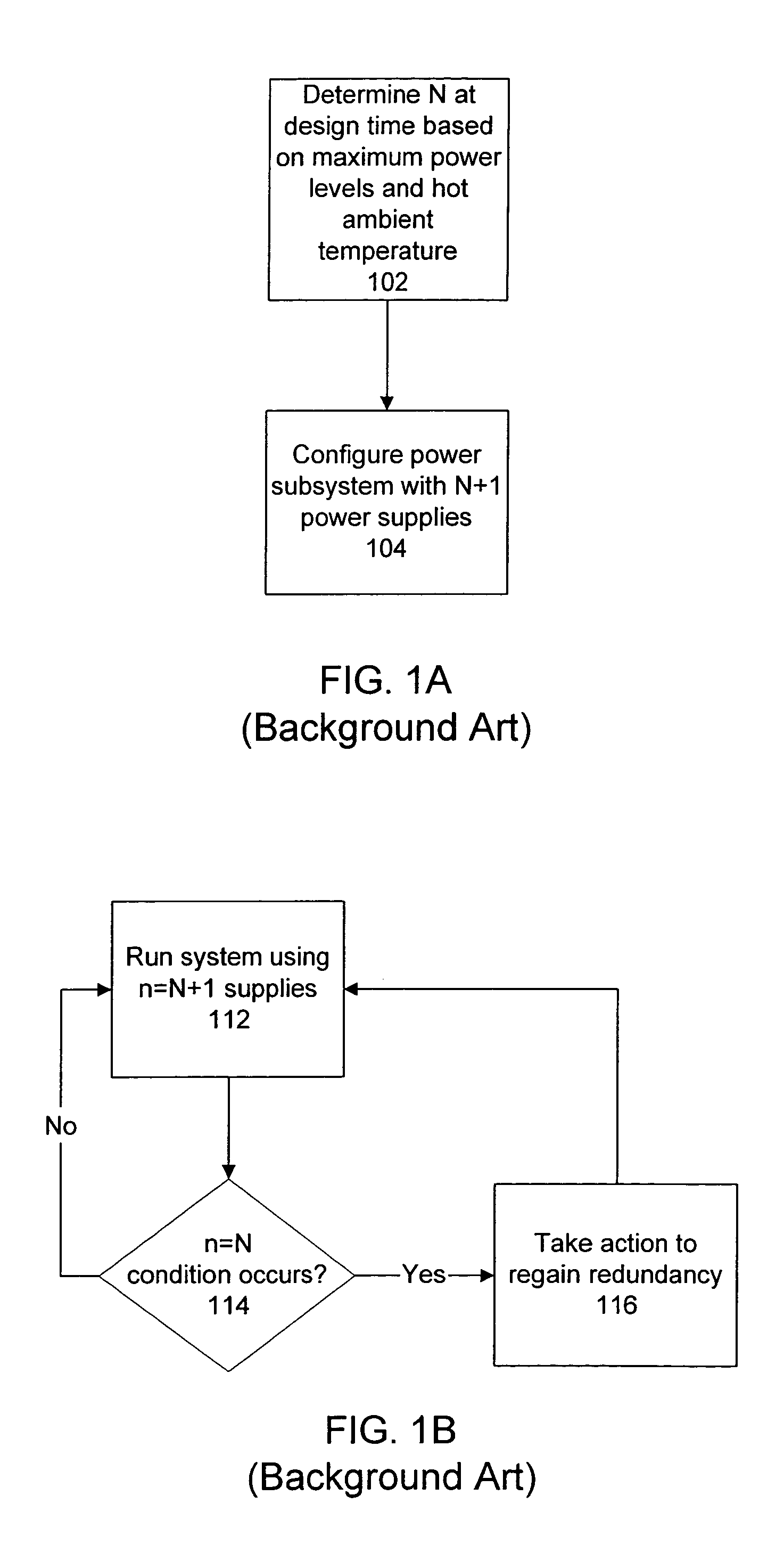
[0017]Consider an example wherein a redundant power subsystem has multiple power supplies of equivalent power supplying capacity. The power subsystem supports a system of devices. Consider an example wherein the number of power supplies that are up and running is “n”, and the system of devices requires “N” power supplies to run without redundancy. If n=N−1, then there is insufficient power to run the system and potential for highly undesirable device failures. On the other hand, if n=N+1, then there is one supply over the minimum needed to run the system. More generally, if n=N+x, then there are “x” supplies over the minimum needed to run the system.

[0018]A conventional redundant power system typically has both N and x statically determined during the system design process. Because the power subsystem may conceivably have to accommodate the maximum load of the system, including components that may be added in the future, the power subsystem is typically designed for the worst possib...


PUM


Abstract

One embodiment disclosed relates to a method of providing dynamic temperature-adjusted power redundancy for a system. Tracking is performed of the number of power supply units, n, that are presently in an up state. The temperature in which the power supply units are operating is measured, and a temperature-adjusted number of power supply units, N, which are presently needed to supply power to the system, is dynamically determined.

Description

BACKGROUND OF THE INVENTION[0001]1. Field of the Invention[0002]The present invention relates generally to power supplies for electronics and computers.[0003]2. Description of the Background Art[0004]Supplying power with back-up or redundancy to computer systems or servers is desirable or required in certain applications. For example, it is becoming increasingly more important to provide mechanisms that minimize unscheduled “down time” in data centers. The term “high availability” (HA) computing is often used to refer to computer systems that include these mechanisms.[0005]HA mechanisms are provided at many levels. For example, a data center may have redundant computer systems so that if one system fails, the workload can be seamlessly shifted to another system. In addition, data may be stored in a disk array subsystem that allows any single disk drive to fail without affecting the ability of the disk array subsystem to continue operating.[0006]One of the most important aspects of H...

Claims


Application Information

Patent Timeline
Patent Type & Authority Patents(United States)
IPC IPC(8): G06F1/26H02J1/10
CPCG06F1/263G06F11/2015H02J1/10H02J1/001
Inventor POMARANSKI, KEN GARYBARR, ANDREW HARVEY
Owner HEWLETT-PACKARD ENTERPRISE DEV LP
Learn More