Self-balancing poppet

a poppet and self-balancing technology, applied in the direction of fluid pressure control, process and machine control, instruments, etc., can solve the problems of shortening affecting causing friction which affects the movement of the poppet, so as to reduce friction and debris, prolong the life of the regulator, and reduce the contact

Inactive Publication Date: 2007-05-29
QUANTUM FUEL SYSTEMS LLC
View PDF8 Cites 17 Cited by
  • Summary
  • Abstract
  • Description
  • Claims
  • Application Information

AI Technical Summary

Benefits of technology

[0007]It is an object of the present invention to provide a poppet that is self-balancing and will return to the seat at the initially formed position for the life of the regulator.

Problems solved by technology

The result is a leak.
Such rubbing creates friction which affects the movement of the poppet.
This not only affects the alignment of the poppet with respect to the seat but also shortens the life of the regulator.
Moreover, debris is produced from the metal-to-metal contact.
Given the high rate of flow, such debris can impact the seat with momentum and carve a leak path, thereby negatively affecting the seal between the poppet and the seat.
As with the contact between the poppet and regulator body, the contact between the spring and regulator body generates debris.
The spring's contact with the poppet can also generate debris.
If such debris is not contained, it can impact the seat with momentum and carve a leak path, thereby negatively affecting the seal between the poppet and the seat.
Having the poppet guided at its end is not advantageous.

Method used


Image

  • Self-balancing poppet
  • Self-balancing poppet
  • Self-balancing poppet

Examples


Embodiment Construction

[0027]In the following description of preferred embodiments, reference is made to accompanying drawings which form a part hereof and in which is shown by way of illustration specific embodiments in which the invention may be practiced. It is to be understood that other embodiments may be utilized and structural changes may be made without departing from the scope of the preferred embodiments of the present invention.

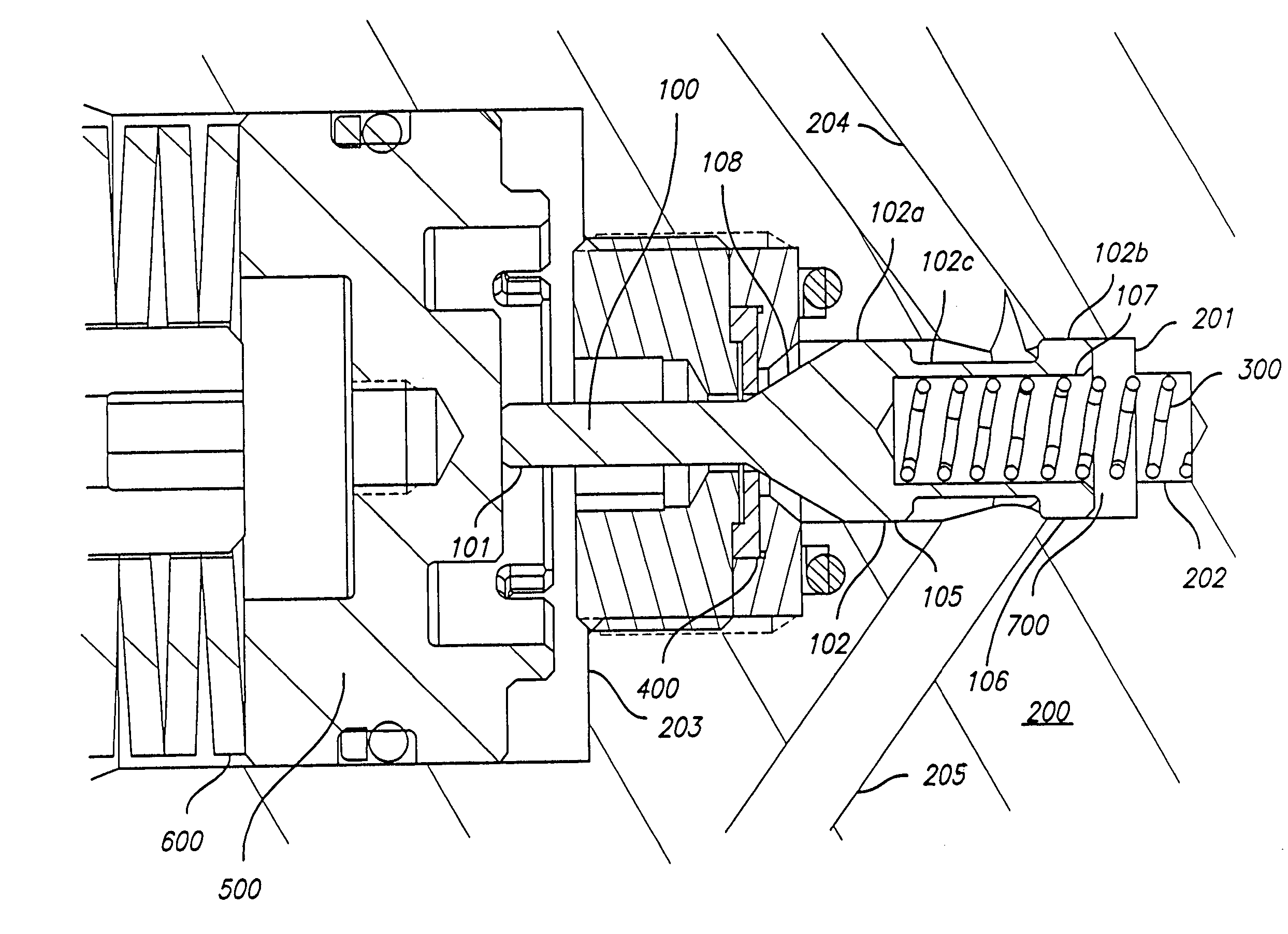
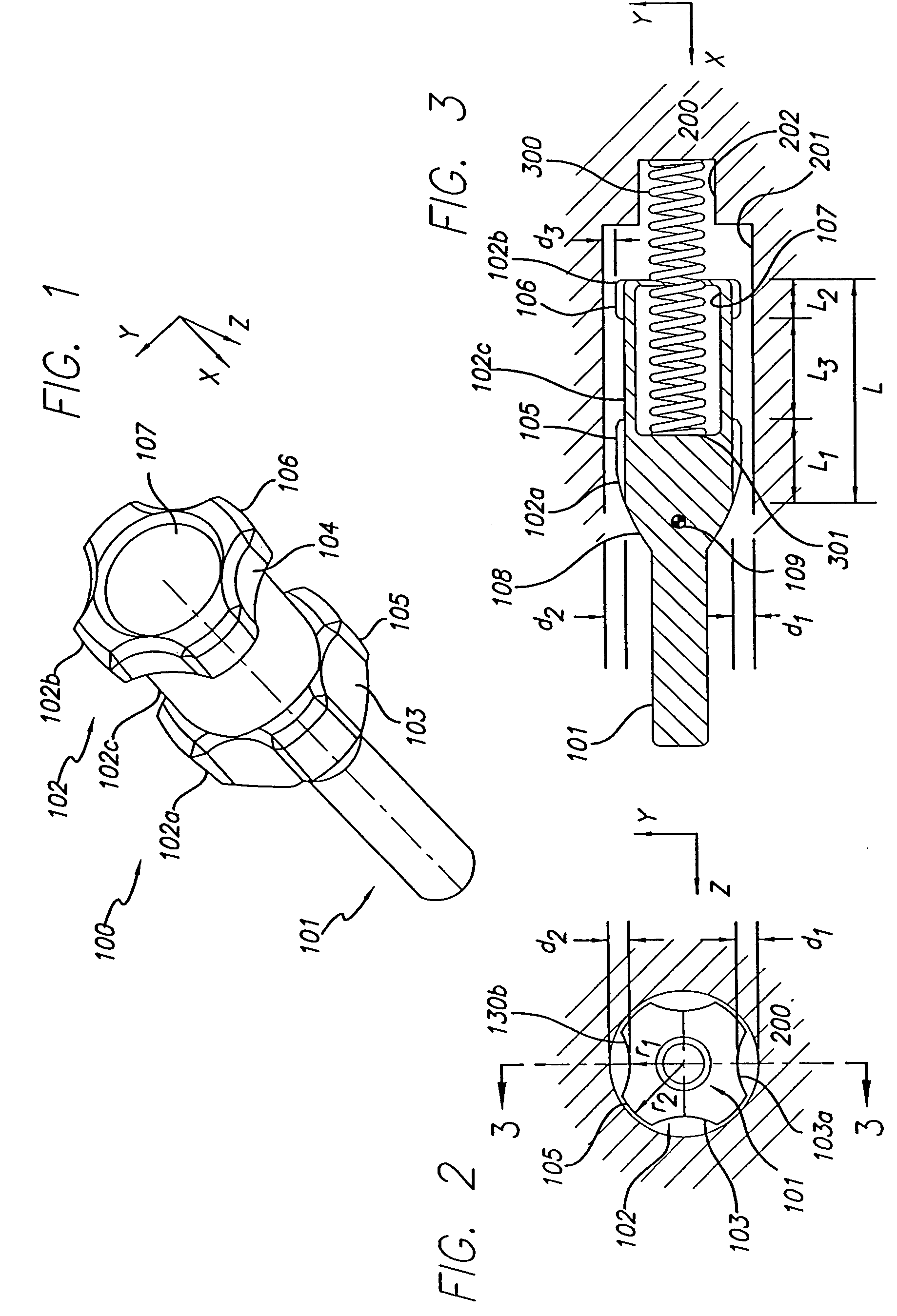
[0028]FIGS. 1–3 illustrate one embodiment of the present invention in different views. The following description will reference all three figures. It should be noted that all figures display the appropriate directional markers. For the purposes of the following description, the x-direction may also be referred to as the axial direction or the longitudinal direction while the y-direction may also be referred to as the vertical direction. It should also be noted that FIG. 1 does not illustrate the regulator body 200 as illustrated in FIGS. 2 and 3 nor the spring 300 as ill...


PUM


Abstract

The present invention is a poppet comprising a stem and a body, with the body having a plurality of channels extending in an longitudinal direction along the periphery of the body. The channels are gas flow conduits that react to the orientation of the poppet and force the poppet to re-align itself during operation with the centerline of the regulator chamber surrounding the poppet. The plurality of channels greatly reduces the contact between the periphery of the poppet and the regulator body. The present invention further includes a bore beginning at the non-stem end of the body and extending in the longitudinal direction within the body of the poppet. The bore can receive a spring for guiding the poppet. By positioning the spring within the poppet, the spring will have minimal contact with the regulator body. The bore avoids the spring from guiding the poppet by its end and adjusts the poppet's center of gravity toward where the poppet sits on the seat. The bore is also a part of a dead zone volume that traps debris.

Description

BACKGROUND OF THE INVENTION[0001]The present invention relates to a self-balancing poppet in a compressed gas flow. The poppet may be used in a regulator in fuel storage and delivery systems.[0002]Compressed gas can be stored in tanks at high pressures such as 10,000 psi. With such high pressures, the pressure of the gas must be reduced before use. To achieve the necessary pressure reduction, a regulator is typically used. The regulator has a seat and a poppet, and the dynamic motion between the seat and poppet provides the necessary pressure reduction. The poppet moves away from the seat to allow the intended outlet pressure to be reached. Once the outlet pressure is reached, the poppet sits on the seat. The contact surface between the poppet and the seat as the poppet sits on the seat seals the compressed gas from the outlet.[0003]The seal produced by the poppet sitting on the seat is formed during the first release of the compressed gas. The poppet is pressed into the seat, which...

Claims


Application Information

Patent Timeline
Patent Type & Authority Patents(United States)
IPC IPC(8): F16K1/12G05D16/02G05D16/10
CPCF16K1/303G05D16/10G05D16/107Y10T137/7826
Inventor CHEN, SHI JUNG
Owner QUANTUM FUEL SYSTEMS LLC
Why Eureka
Try Eureka