Tooth form design for reciprocating saw blade

a reciprocating saw blade and blade technology, applied in the field of saw blades, can solve the problem of fast cutting of the saw blade through the material

Active Publication Date: 2007-06-05
BLACK & DECKER INC
View PDF102 Cites 104 Cited by
  • Summary
  • Abstract
  • Description
  • Claims
  • Application Information

AI Technical Summary

Problems solved by technology

Secondly, the user is concerned with the speed of the saw blade, how fast the saw blade cuts through the material.

Method used


Image

  • Tooth form design for reciprocating saw blade
  • Tooth form design for reciprocating saw blade

Examples


Embodiment Construction

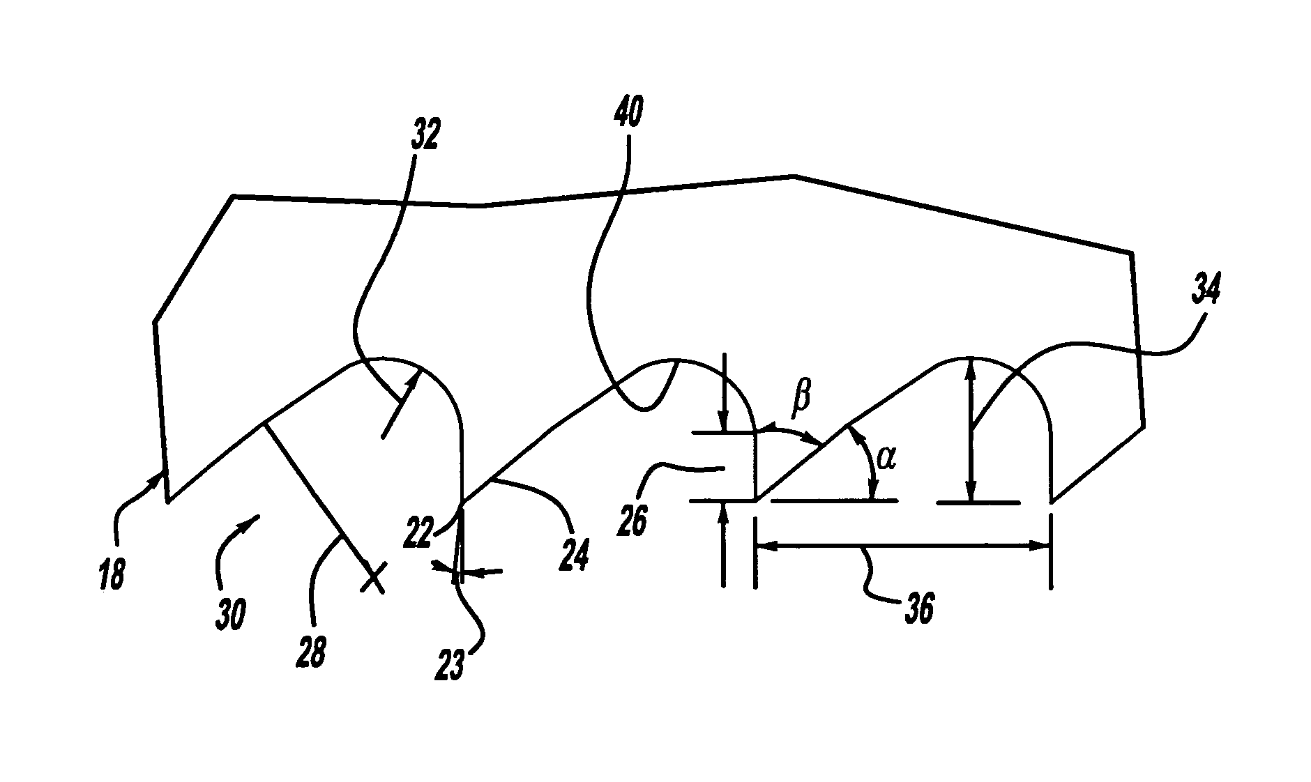
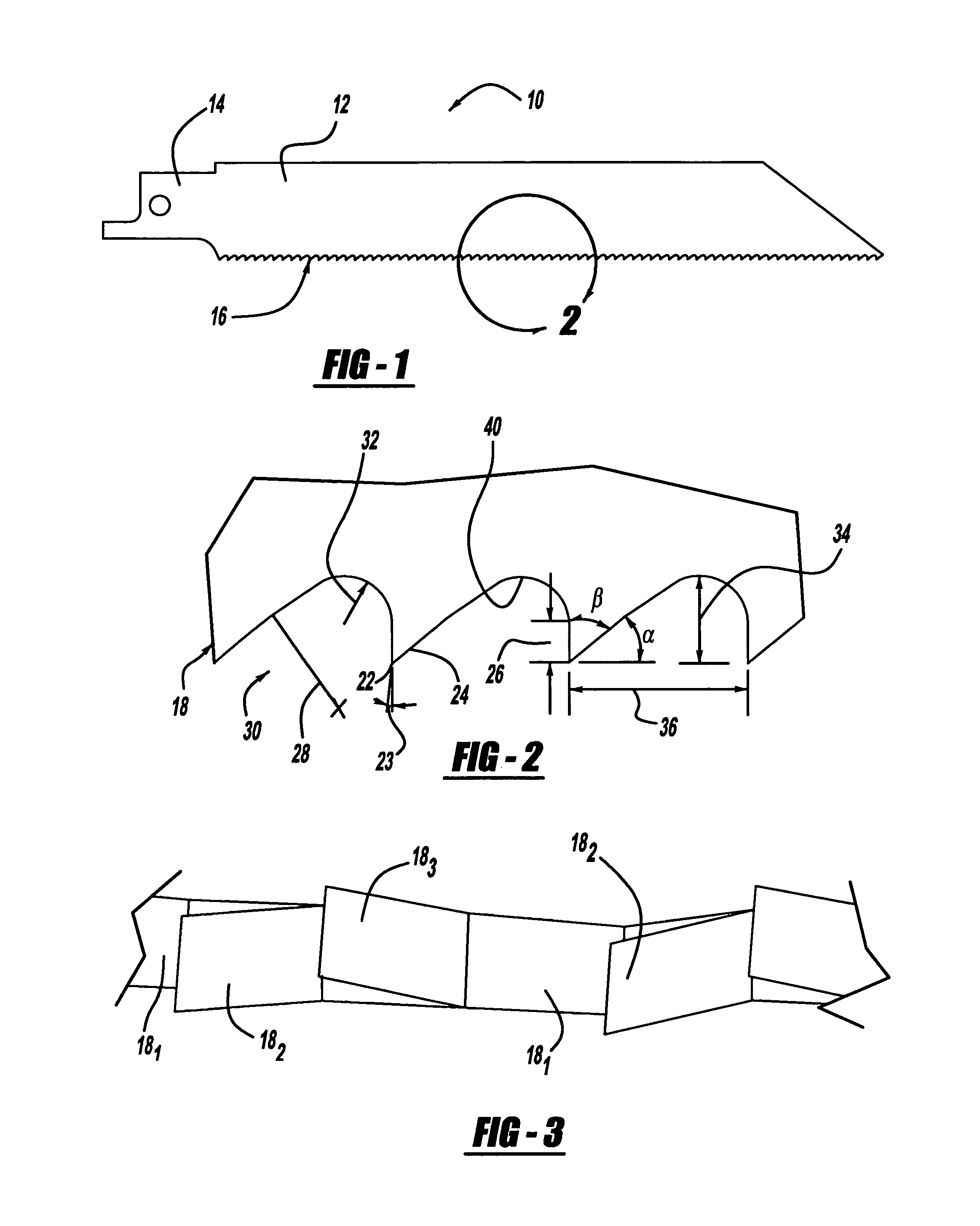
[0011]Turning to the figures, a reciprocating saw blade is illustrated and designated with the reference numeral 10. The saw blade 10 includes a body 12, a connecting portion 14, and a cutting portion 16. The cutting portion 16 includes a plurality of teeth 18. The teeth 18 can have a raker style set wherein a first tooth 181 is neutral or in the plane of the body 12 with a second tooth 182 offset to the left and a third tooth 183 offset to the right with a repeating pattern as seen in FIG. 3.

[0012]Turning to FIG. 2, an enlarged tooth form is illustrated. The tooth 18 has a rake face 22 and a relief face 24. The rake face 22 is ordinarily perpendicular to the horizon and thus is a zero angle rake face. However, the rake angle 23 may be modified up to a 3° rake face angle. The rake face 22 or land has a tooth depth identified by the numeral 26. The relief face 24 is defined by a relief angle a of between 38°-42°. Preferably, the relief angle is about 40°. The relief face 24 is contin...


PUM

PropertyMeasurementUnit
included angleaaaaaaaaaa
rake face angleaaaaaaaaaa

Abstract

A reciprocating saw has a tooth form that decreases the cutting time of the saw blade and extends the life of the saw blade. The tooth height is longer than conventional metal cutting reciprocating saws. Also, the tooth form has a larger gullet. The tooth rake angle remains substantially constant during the life of the saw blade.

Description

BACKGROUND OF THE INVENTION[0001]The present invention relates to saw blades and, more particularly, to a tooth form for reciprocating saw blades.[0002]Reciprocating saws are utilized to cut metallic and wooden materials. Ordinarily, when utilizing a reciprocating saw blade, the user generally looks at various aspects of the saw blade. When choosing a reciprocating saw blade, the user considers the expectant life of the saw blade; how many cuts before saw blade replacement occurs. Secondly, the user is concerned with the speed of the saw blade, how fast the saw blade cuts through the material. Next the user considers the durability of the saw blade; how long it will last under normal wear and tear. Finally, the user is concerned with the accuracy of the saw blade; how well will the saw blade follow its intended line of cut.[0003]The present invention provides the art with a reciprocating saw blade utilized for cutting a metallic material. The saw blade increases the life of the saw ...

Claims


Application Information

Patent Timeline
Patent Type & Authority Patents(United States)
IPC IPC(8): B27B33/02B23D63/00
CPCB23D61/121Y10T83/935Y10T83/9346Y10T83/9367Y10T83/9319Y10T83/9358
Inventor ROMPEL, MARKUSGEORGE, MALEKTHOMAS, RICKEY
Owner BLACK & DECKER INC
Why Eureka
Try Eureka