
Short corridor progressive addition lenses with reduced unwanted astigmatism

a technology of progressive addition and short corridor, applied in the field of multi-focal ophthalmic lenses, can solve the problems of affecting the wearer's vision, and affecting the wearer's vision, and achieving the effect of reducing the number of unwanted astigmatism

Inactive Publication Date: 2007-06-12
ESSILOR INT CIE GEN DOPTIQUE
View PDF9 Cites 73 Cited by
  • Summary
  • Abstract
  • Description
  • Claims
  • Application Information

AI Technical Summary

Benefits of technology

The solution results in lenses with a shorter corridor length and lower unwanted astigmatism, providing improved vision stability and flexibility in frame sizes without significant changes in distance or near vision powers, allowing for better adaptation to different frame sizes.

Problems solved by technology

However, an inherent disadvantage of PALs is the presence of unwanted astigmatism, or astigmatism that is undesirable and is introduced or caused by one or more of the lens' surfaces.
Unwanted astigmatism can produce swim, image magnification, and motion effects for the lens wearer that disrupts the wearer's vision.
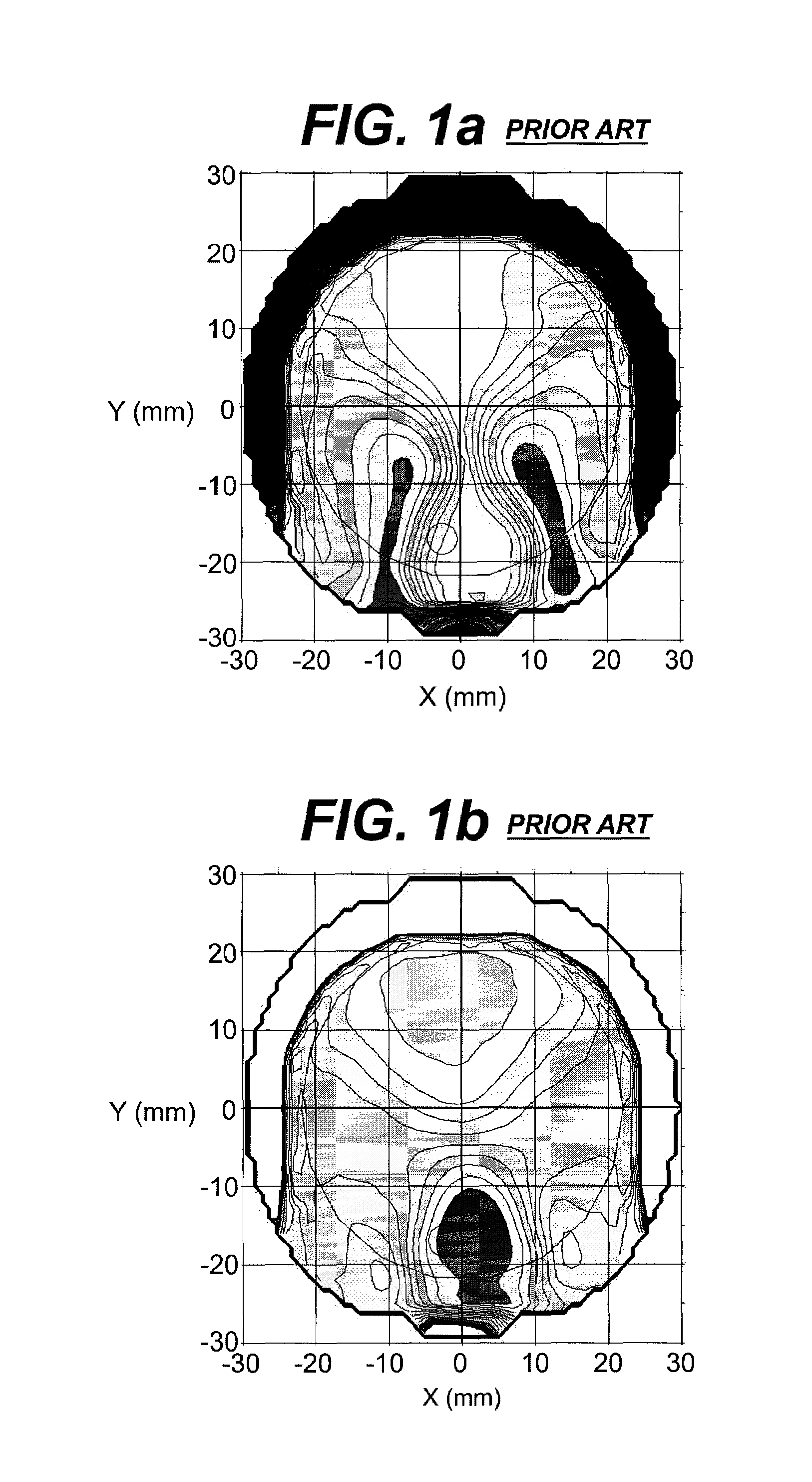
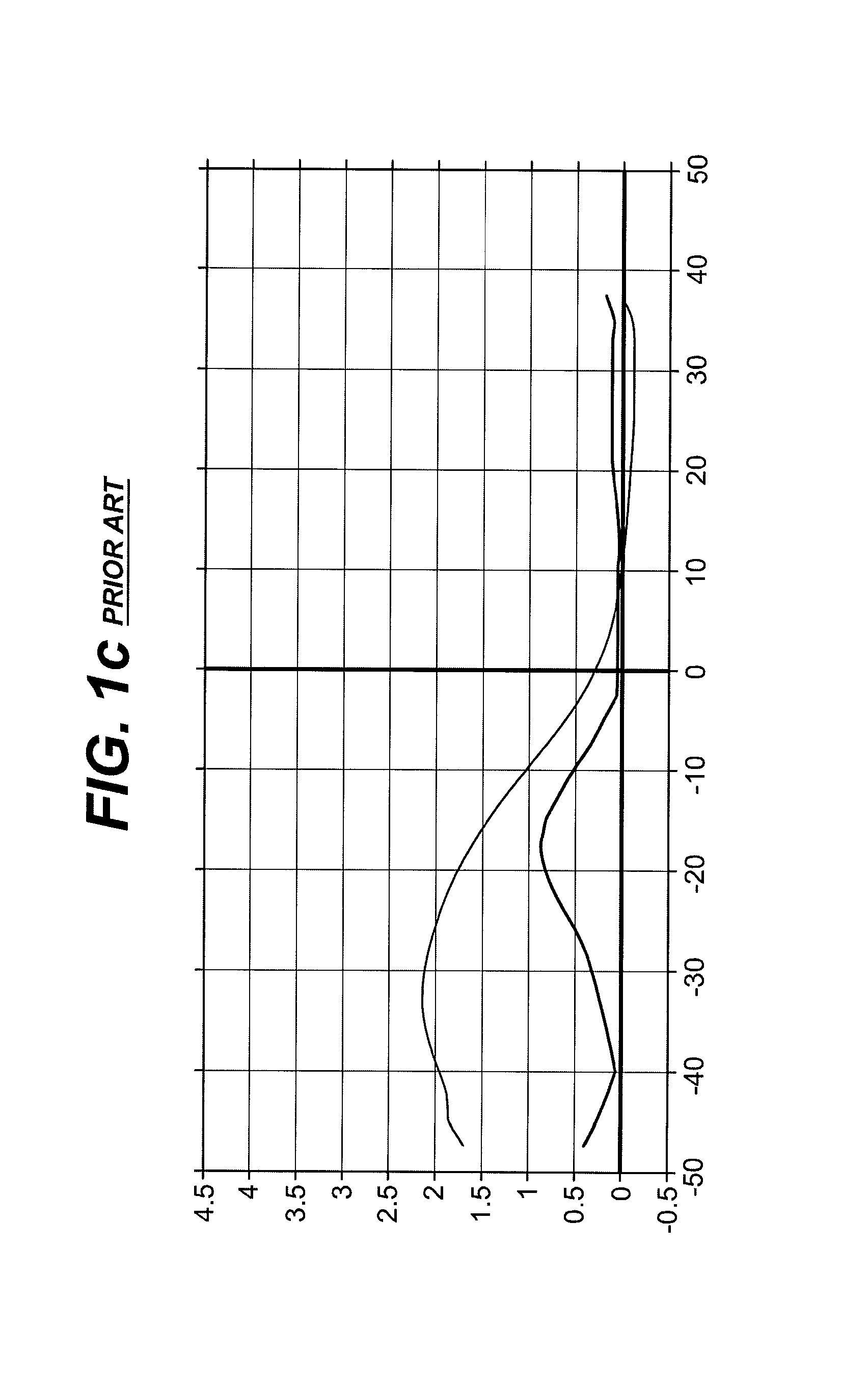
Some PAL lenses have been designed with short corridors in the 9 mm to 12 mm range, but these PALs typically have much higher levels of unwanted astigmatism.
If a PAL wearer has become accustomed to a particular design in a standard size frame and then chooses to switch to a smaller frame, typically the ECP must switch the patient into another PAL brand, which may result in wearer adaptation problems.

Method used


Image

  • Short corridor progressive addition lenses with reduced unwanted astigmatism
  • Short corridor progressive addition lenses with reduced unwanted astigmatism
  • Short corridor progressive addition lenses with reduced unwanted astigmatism

Examples


example 1

[0057]A first progressive surface was designed using a material with a refractive index of 1.515. The lens' base curve was 104.3 mm and the add power was 2.04 diopters. This surface had a standard length corridor of 12.3 mm and maximum unwanted astigmatism is 1.56 diopters. The corridor factor Cf was 9.40 mm. The surface U was scaled with the following scaling factor: u(x,y)=1.019*U(x,y).

[0058]A second progressive surface having the same refractive index, base curve, add power, corridor length, corridor factor and maximum unwanted astigmatism as the first surface was also designed. The second surface was scaled to a lower add power with the following scaling factor v(x,y)=1.045*U(x,y) according to the design methodology of the invention.

[0059]The first and second surfaces were added using the blending function F of Equation. III with a=−0.001466 and b=0.018. The addition and blending result in the following equation for the resulting progressive surface w(x,y):

[0060]w⁡(x,y)=⁢1.019*u...

example 2

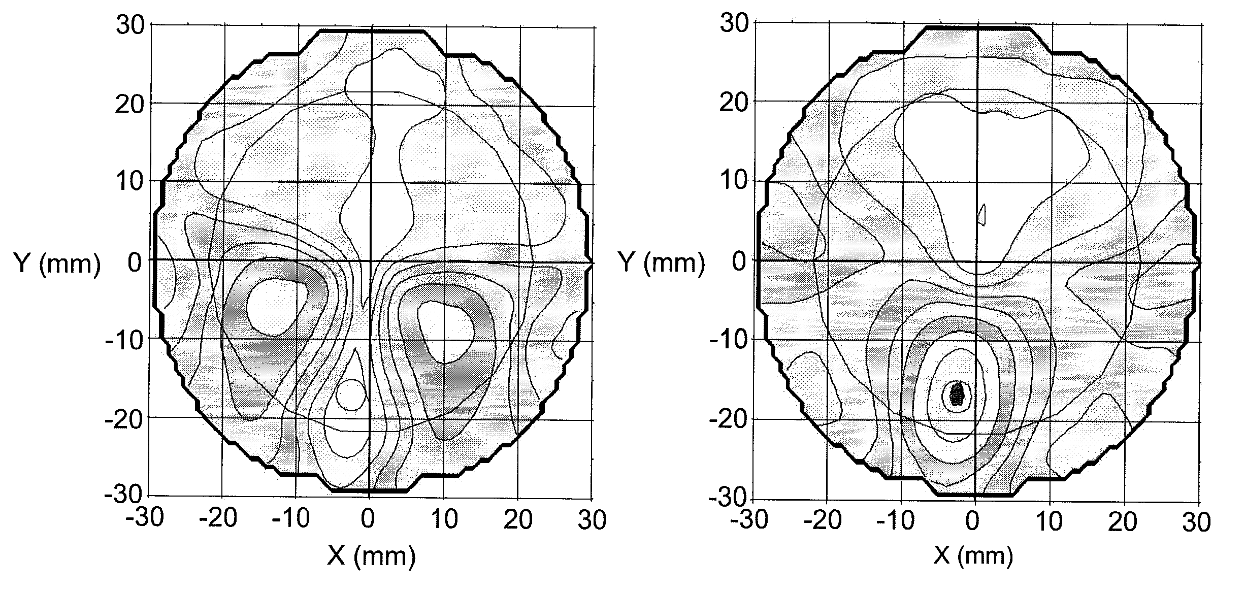
[0062]The surface (W) of Example 2 was shifted vertically so that the fitting point was located at y=+2 mm. The optical data for the resulting progressive surface (W) is shown in Table 1. The power and cylinder contour plots are shown in FIGS. 5a and 5b and the power and cylinder profile along the corridor in FIG. 5c. This resulted in the lengthening of the corridor by 2 mm to 12.4 mm which is similar to a conventional standard corridor length progressive design. The maximum unwanted astigmatism increases by only 0.05 diopters to 1.63 diopters. The corridor factor, Cf was 9.96 mm. The fitting point was marked at y=+2 mm.

[0063]

TABLEOpticalLensLensLensSurface ASurface WExampleParameter123Example 1Example 12Add Power2.042.152.042.042.012.03(D)Distance7.918.313.525.26.323.4Width (mm)Reading18.311.216.216.014.115.8Width(mm)Reading13.89.58.09.27.48.2PowerWidth(mm)Corridor11.610.512.312.310.412.4Length(mm)Corridor6.65.48.68.47.06.6Width(mm)Max.2.642.361.531.561.581.63Astig.(D)Cf (mm)15.011...


PUM


Abstract

The invention provides lenses produced by the adding of two or more surfaces, in which lenses both the length of the corridor is shortened and the maximum unwanted astigmatism is reduced.

Description

FIELD OF THE INVENTION[0001]The present invention relates to multifocal ophthalmic lenses. In particular, the invention provides progressive addition lens designs with both a shortened corridor and reduced unwanted astigmatism.BACKGROUND OF THE INVENTION[0002]The use of ophthalmic lenses for the correction of ametropia is well known. For example, multifocal lenses, such as progressive addition lenses (“PALs”) are used for the treatment of presbyopia. PALs have at least one progressive surface that provides far, intermediate, and near vision in a gradual, continuous progression of vertically increasing dioptric power from far to near focus, or top to bottom, of the lens.[0003]PALs are appealing to the wearer because PALs are free of the visible ledges between the zones of differing dioptric power that are found in other multifocal lenses, such as bifocals and trifocals. However, an inherent disadvantage of PALs is the presence of unwanted astigmatism, or astigmatism that is undesirab...

Claims


Application Information

Patent Timeline
Patent Type & Authority Patents(United States)
IPC IPC(8): G02C7/06G02C7/02
CPCG02C7/024G02C7/061G02C7/063
Inventor MENEZES, EDGAR V.
Owner ESSILOR INT CIE GEN DOPTIQUE
Learn More