
Centrometer

A technology of interpupillary distance meter and pattern, applied in the field of interpupillary distance meter, can solve the problems of limited measurement data, low accuracy, unscientific, etc., and achieve the effect of extensive and comprehensive measurement data and ensuring accuracy.

Active Publication Date: 2013-03-13
SHENZHEN HENGXING SHIGUANG TECH
View PDF8 Cites 9 Cited by
  • Summary
  • Abstract
  • Description
  • Claims
  • Application Information

AI Technical Summary

Problems solved by technology

Measuring pupillary distance with a pupillary distance ruler is unscientific, with low accuracy and limited measurement data; the pupillary distance meter is improved compared with the pupillary distance ruler, but the measurer must hold the pupillary distance meter in front of the patient's eyes with both hands, and the patient's eyes can pass through the affected area. Check the window, and at the same time, the examiner observes the patient's eyes from the inspection window with one eye, manually adjusts the reference object on the inspected window to the center of the reflective point of the patient's eye, and measures the interpupillary distance
During the measurement, the natural shaking of the examiner's hand will affect the accuracy of the measurement, and the measurement data is also limited; the computer refractor measures the pupil distance while measuring the patient's diopter, which is very convenient to operate, but the patient must keep his head still, otherwise it will It greatly affects the measurement accuracy, and the measurement data of the computer refractometer is also limited, so it cannot be used alone for fitting bifocal progressive mirrors

Method used


Image

  • Centrometer
  • Centrometer
  • Centrometer

Examples


Embodiment Construction

[0015] Specific embodiments of the present invention will be described in further detail below based on the accompanying drawings. It should be understood that the specific embodiments described here are merely examples and are not intended to limit the protection scope of the present invention.

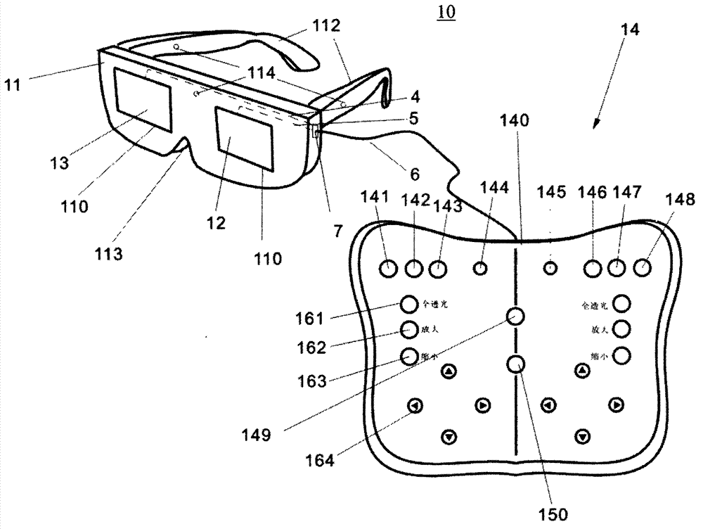
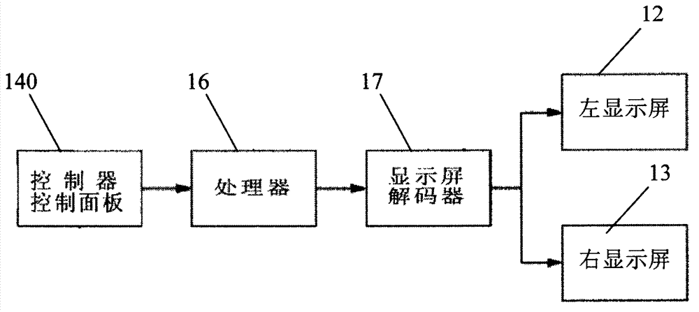
[0016] see figure 1 , shows the interpupillary distance meter 10 of Embodiment 1 of the present invention, which includes a bracket 11 for wearing, and also includes a control unit and a display device located on the bracket 11. The display device of this embodiment includes a left display screen 12 and a right display Screen 13, the control unit is electrically connected with the display device, and is used to control the left display screen 12 and the right display screen 13 to display patterns for visual inspection and measure visual data.

[0017] Such as figure 1 As shown, the interpupillary distance meter 10 includes a manipulator 14 with function keys. The control unit of t...


PUM


Abstract

The invention relates to a centrometer, which comprises a bracket for wearing, a control unit and a display device, wherein the display device is arranged on the bracket; and the control unit is electrically connected with the display device, and is used for controlling the display device to display the shape and position of a pattern for visual detection and to measure visual data. According to the centrometer, a visual detection image is displayed by using a display screen, and the shape and position of the visual detection image are controlled by using the control unit, so that an interpupillary distance can be measured accurately, and the centrometer is very safe for human eyes. Moreover, the centrometer can also be used for rapidly and accurately measuring the interpupillary distance when double eyes watch along a plurality of directions, the interpupillary distance and the like when a single eye watches along a plurality of directions, and the relative position relation of the left eye or right eye vision center of binocular vision or mono-vision. The centrometer can be further used for measuring the interpupillary distance and the position relation thereof conveniently during fitting of double-light or multi-light progressive addition lenses; and moreover, the centrometer is used for measuring the stress situation of ciliary muscle on the aspects of ophthalmology medicine and research and assisting in correcting strabismus.

Description

technical field [0001] The invention relates to a visual detection instrument, in particular to a pupillary distance instrument. Background technique [0002] Eyes are the windows to the soul of human beings. Human beings use their eyes all the time. They must use their eyes in life, work and study. However, as computers enter thousands of households and the popularity of the Internet, people's eyes are more likely to be damaged. In order to protect the eyes, regular inspection of vision is an important link. For example, the problem of measuring the interpupillary distance is often involved in the inspection of medical treatment, optical glasses, cosmetology, and facial features, which needs to be measured by the interpupillary distance meter. [0003] The traditional tools for measuring the pupillary distance include: the pupillary distance ruler, the pupillary distance meter, and the computer refractor. Measuring pupillary distance with a pupillary distance ruler is un...

Claims


Application Information

Patent Timeline
Patent Type & Authority Applications(China)
IPC IPC(8): A61B3/11
CPCA61B3/111
Inventor 黄立贤
Owner SHENZHEN HENGXING SHIGUANG TECH
Learn More