
Progressive addition lenses with an additional zone

a technology of progressive addition and lens, applied in the field of multi-focal lenses, can solve the problems of affecting the visual effect of objects outside the near vision range, and affecting the visual effect of objects viewed through this portion of the lens,

Inactive Publication Date: 2005-05-05
ESSILOR INT CIE GEN DOPTIQUE
View PDF6 Cites 8 Cited by
  • Summary
  • Abstract
  • Description
  • Claims
  • Application Information

AI Technical Summary

Problems solved by technology

Because of this, viewing of objects through this portion of the lens, which objects are outside of the near vision range, are problematic.
However, this does not achieve the objective of providing clear visualization of the ground or stairs.
If the rate of decrease is faster, in addition to significant unwanted astigmatism, prism and magnification changes cause objects viewed through this zone to shift and change in size.

Method used


Image

  • Progressive addition lenses with an additional zone
  • Progressive addition lenses with an additional zone
  • Progressive addition lenses with an additional zone

Examples


example 1

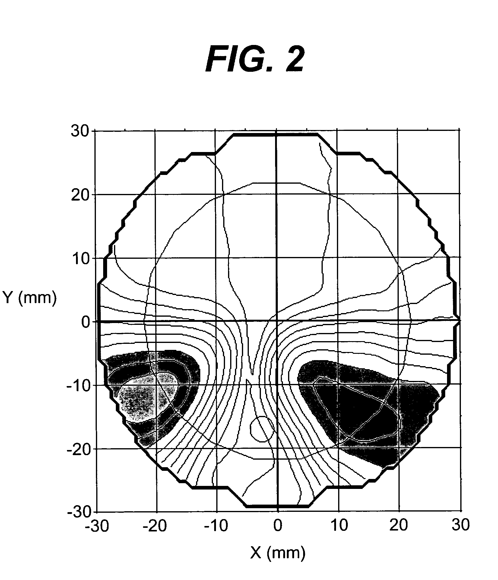
[0028] A 1.498 refractive index conventional progressive addition lens, Varilux COMFORT™ lens, is provided with a convex progressive addition surface and a concave spherical surface. The convex surface distance vision zone curvature is 5.25 diopters and the near vision zone curvature is 7.25 diopters. The channel length is 16 mm. The lens distance power is 0.00 diopters and the dioptric add power is 2.00 diopters. The power contour map for the lens is depicted in FIG. 2, the astigmatic contour map is depicted in FIG. 3., and the channel power profile is depicted in FIG. 4. Line A in the Figure is the add power profile and line B is the unwanted astigmatism. The power remains constant from the beginning of the near vision zone, at about 15 mm below the fitting point, through the lens edge at about 25 mm below the fitting point.

example 2

[0029] A 1.586 refractive index lens of the invention is provided with a convex progressive addition surface with a distance vision zone curvature of 5.60 diopters, a near vision zone curvature of 7.60 diopters resulting in a lens with dioptric add power of 2.00 diopters and a channel length of 17 mm. A fourth zone is designed as a convex spherical surface with a power of 0.78 diopters. An offset, ο=0.31 mm and a tilt, T=0.9 degrees is used to match the curvatures of the spherical and progressives surfaces at their boundary. The blending function, F(x,y) is shown in Table 1. The power of the additional zone reaches 0.78 diopters at 22.5mm below the fitting point. The additional zone is blended along the prime meridian with the near power, but there are peripheral discontinuities on either side of the zone resulting in increased unwanted astigmatism and image jump. The power contour map for the lens is depicted in FIG. 5, the astigmatic contour map is depicted in FIG. 6, and the chan...


PUM


Abstract

The invention provides multifocal lenses containing at least four zones of refractive power. The zones are positioned such that the wearer is able to use the inferior-most portion of the lens to clearly view objects at distances more than about 45 cm from the eye.

Description

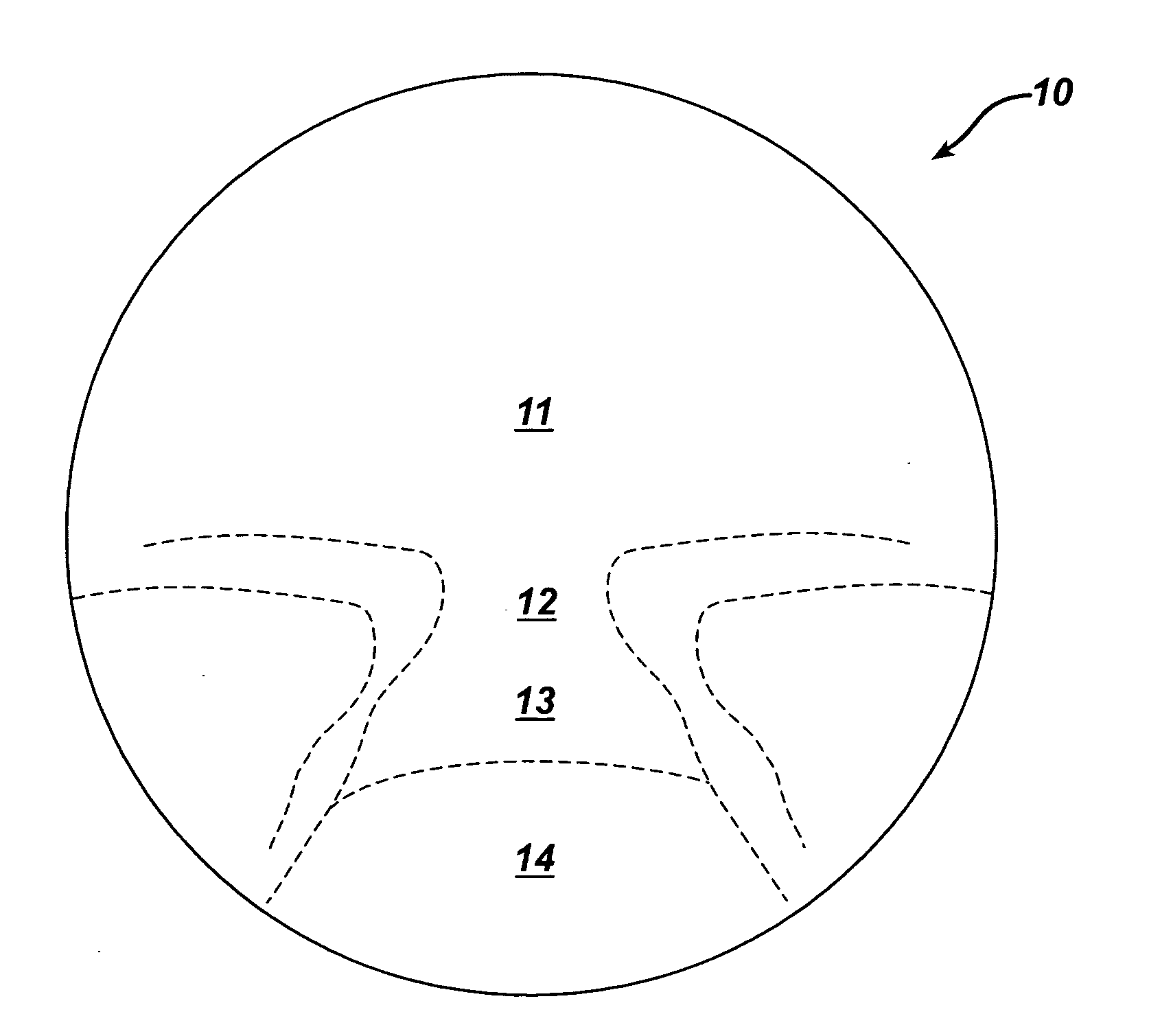
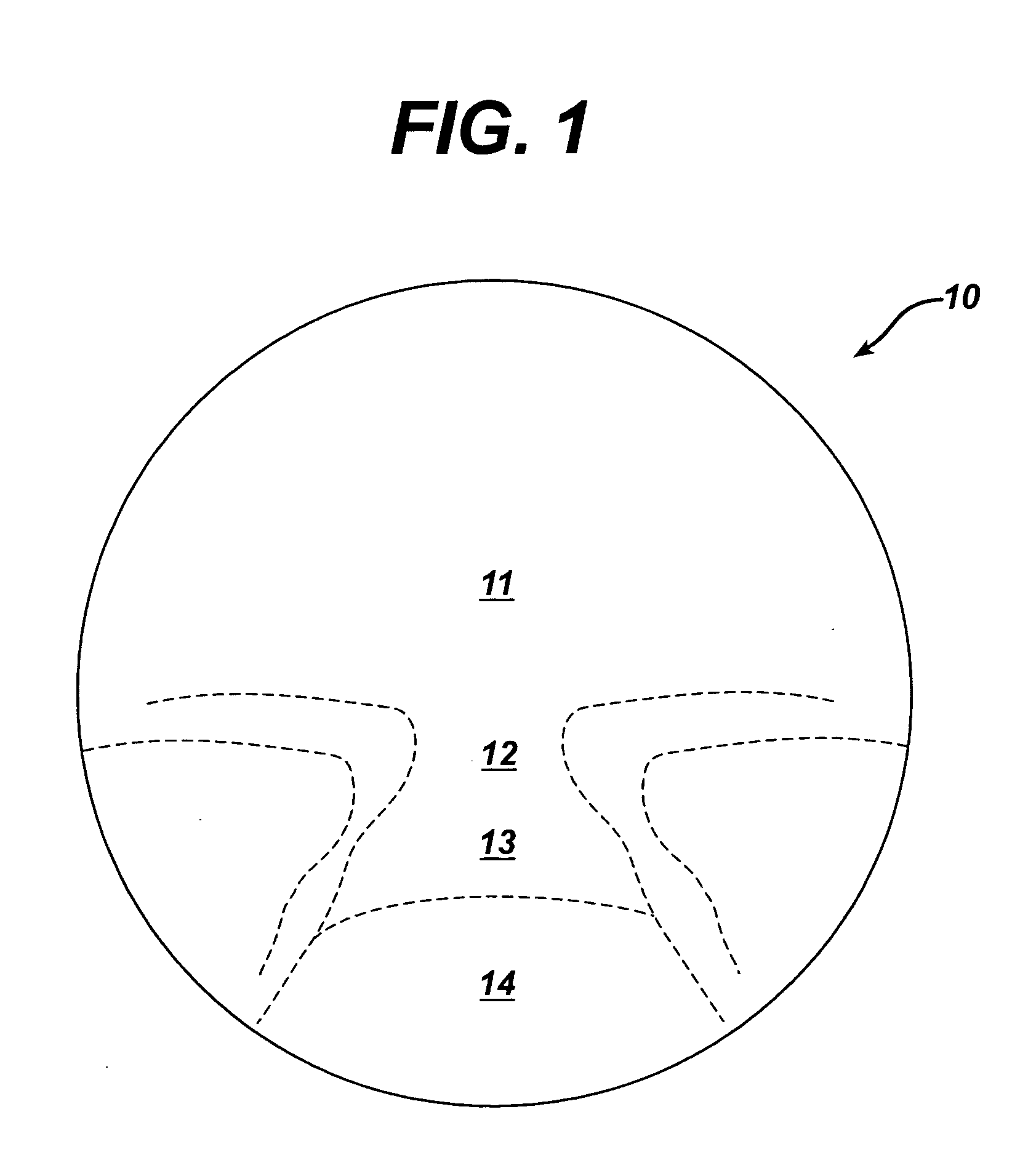
FIELD OF THE INVENTION [0001] The present invention relates to multifocal lenses. In particular, the invention provides a multifocal lens that has a zone in addition to the distance, intermediate and near zones, which zone is located inferior to the near zone. BACKGROUND OF THE INVENTION [0002] The use of ophthalmic lenses for the correction of ametropia is well known. For example, multifocal lenses, such as progressive addition lenses (“PALs”), are used for the treatment of presbyopia. Typically, the progressive surface of a PAL has three zones, one zone each of distance, intermediate, and near vision power. The distance vision power zone permits viewing of objects located at more than 70 cm from the viewer, while the intermediate zone permits viewing of objects at between 45 and 70 cm, such as a computer monitor and the near vision power zone permits viewing of objects at less than about 45 cm. The boundaries between each of these zones are typically continuous and blended so that...

Claims


Application Information

Patent Timeline
Patent Type & Authority Applications(United States)
IPC IPC(8): G02C7/02G02C7/06
CPCG02C7/06G02C7/066G02C7/063G02C7/061
Inventor MENEZES, EDGAR V.
Owner ESSILOR INT CIE GEN DOPTIQUE
Learn More