Distortion free image capture system and method

a free, image technology, applied in the field of distortion free image capture system and method, can solve the problems of not teaching how one skilled in the art might enable correction of all, common distortion in all lenses, and prior art failing to teach how to simultaneously correct for errors in cameras, lenses, lighting systems, etc., to achieve greater distortion, reduce camera costs, and reduce cost

Inactive Publication Date: 2002-04-11
LEWIS JR CLARENCE A +1
View PDF6 Cites 160 Cited by
  • Summary
  • Abstract
  • Description
  • Claims
  • Application Information

AI Technical Summary

Benefits of technology

0075] (3) To reduce costs of cameras, lenses, and lighting systems by incorporating lower cost alternatives that by themselves introduce greater distortions, but result in significantly lower distortions when incorporated in a camera, lens, and lighting system that employ the subject of this disclosure.
0076] (a) The substitution of low co...

Problems solved by technology

While the prior art teaches some forms of image correction, the prior art is deficient in that there is no teaching of how one skilled in the art might enable correction of all the known types of optical and electronic distortion that are present in a modern image capturing system.
Specifically, the prior art fails to teach how it is possible to simultaneously correct for errors in the cameras, lenses, and lighting systems that are present within a modern image capturing system.
This is a common distortion in all lenses that arises from dispersion of the RED, GREEN and BLUE planes.
It appears as registration errors between the RED, GREEN, and BLUE are particularly noticeable at higher magnifications and at the extremities of the image.
All conventional lenses produce geometric distortions in images that are off axis to the lens.
However, in a zoom lens these distortions are subs...

Method used


Image

  • Distortion free image capture system and method
  • Distortion free image capture system and method
  • Distortion free image capture system and method

Examples


Embodiment Construction

Embodiments are Exemplary

[0122] While the present invention is susceptible of embodiment in many different forms, there is shown in the drawings and will herein be described in detailed preferred embodiment of the present invention with the understanding that the present disclosure is to be considered as an exemplification of the principles of the invention and is not intended to limit the broad aspect of the invention to the embodiment illustrated.

[0123] The numerous innovative teachings of the present application will be described with particular reference to the presently preferred embodiments, wherein these innovative teachings are advantageously applied to the particular problems of a DISTORTION FREE IMAGE CAPTURE SYSTEM AND METHOD. However, it should be understood that these embodiments are only examples of the many advantageous uses of the innovative teachings herein. In general, statements made in the specification of the present application do not necessarily limit any of t...


PUM


Abstract

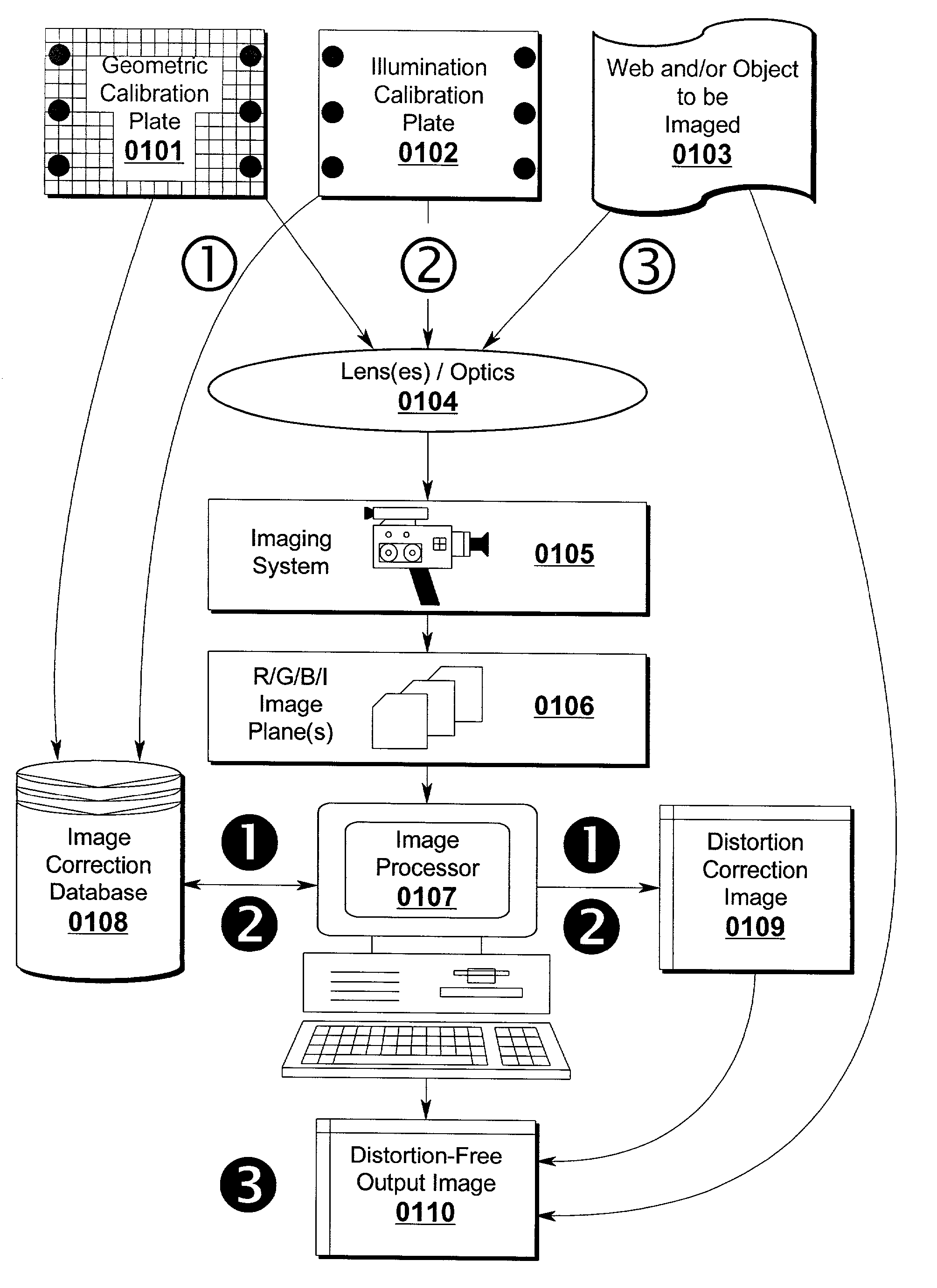
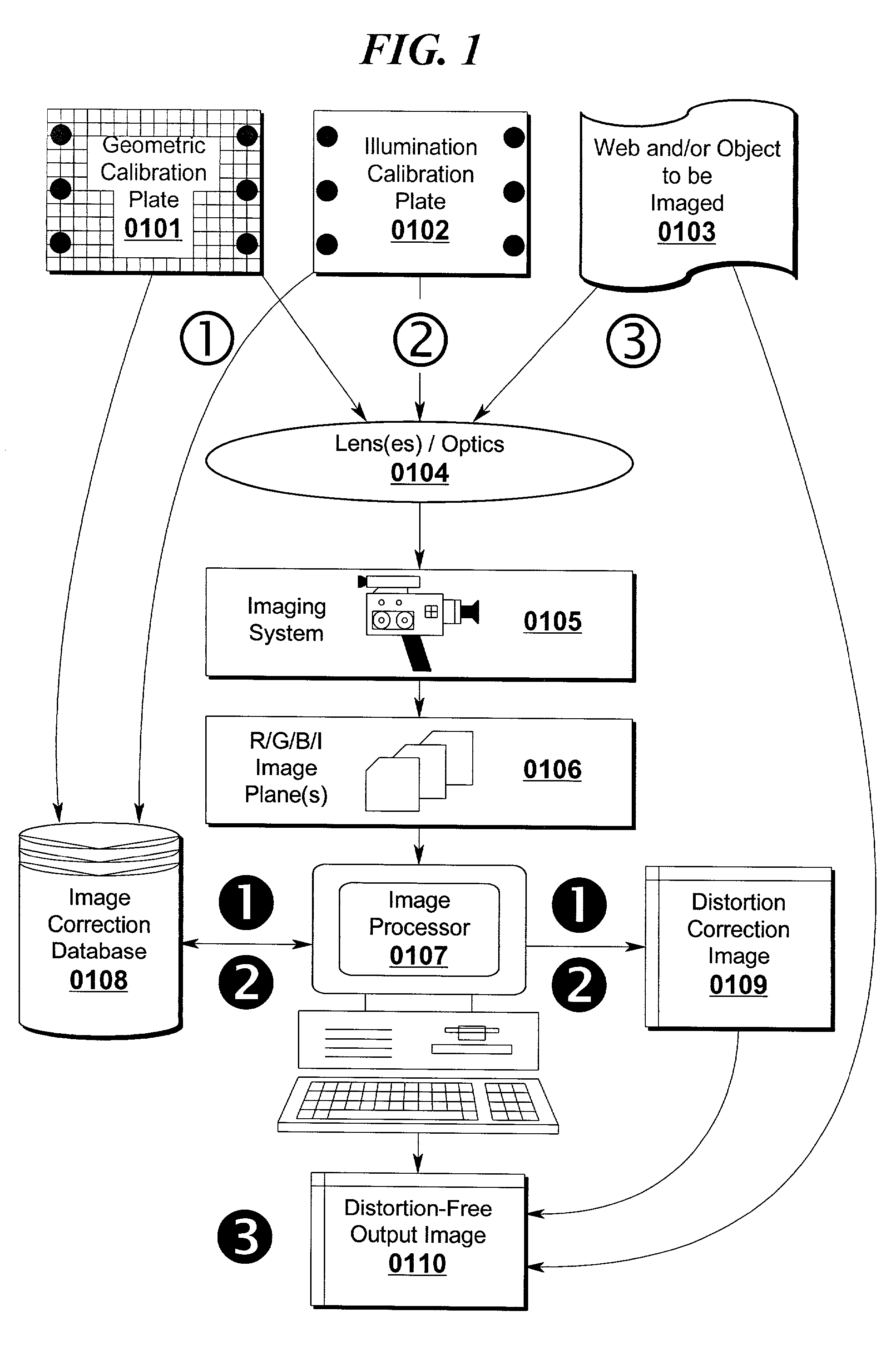
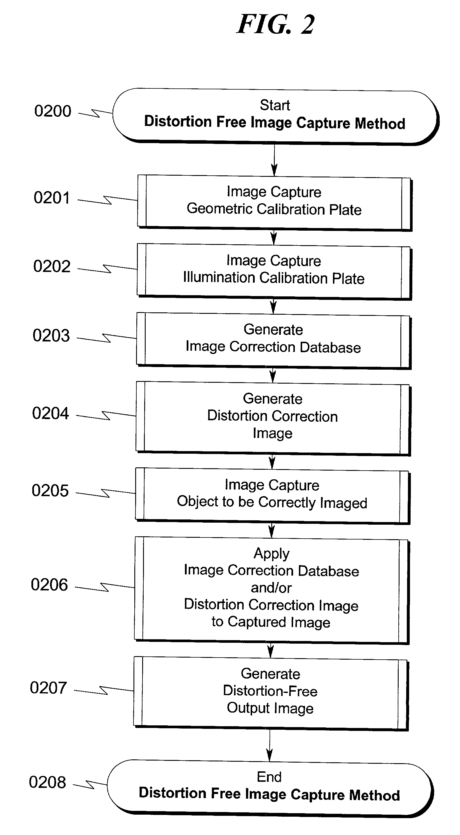
A system and method for correcting distortions that occur in image capture systems is disclosed. The present invention in some preferred embodiments includes provisions to correct or change magnification differences for all causes including position errors in zoom lens positioning mechanisms as well as those caused by chromatic aberration, CCD alignment errors, lens distortion off center variations, pincushion/barrel lens distortion, magnification distortions, camera and lens misalignment errors, and lighting variations (including flash-to-flash illumination variations). A significant feature of the present invention in contrast with the prior art is that with the use of a movable calibration plate in the present invention it is possible to image capture both the calibration plate and the input object image in a single image capture, thus permitting simultaneous compensation for a variety of lighting and illumination variations not possible with the prior art.

Description

[0001] The present invention is related in the general area of image capture and processing systems where images of objects are obtained using cameras, computers, and lighting systems that are then processed through software for a variety of measurement and control applications.[0002] Various distortions inherent in cameras, lenses, mounting and lighting systems produce inaccuracies between the object and its stored image thus limiting applications of image capture and image processing where accurate measurement and control of objects is required.[0003] The present invention provides a means for the measurement and correction of all combined geometric distortions of a camera, lens, lighting and computer system that produce a distortion free computer image at the correct magnification that is an exact duplication of the object from which the computer image is generated. The present invention eliminates distortions that are inherent in cameras, all types of lenses and lens systems inc...

Claims


Application Information

Patent Timeline
IPC IPC(8): G06F17/30G06T3/00H04N5/217
CPCH04N5/217H04N23/81
Inventor LEWIS, CLARENCE A. JR.LEWIS, RICHARD DALE
Owner LEWIS JR CLARENCE A
Why Eureka
Try Eureka