Fastening assembly with improved handling properties

a technology of handling properties and fastening, which is applied in the field of fastening assemblies, can solve the problems of not being able to completely tighten down the screw, difficult or impossible to drill perpendicularly, and difficult to drill perpendicularly in the wall or ceiling, and achieve the effect of tightening the frictional press and stable play-free anchoring of the bone bra

Inactive Publication Date: 2007-06-12
BIEDERMANN TECH GMBH & CO KG
View PDF15 Cites 57 Cited by
  • Summary
  • Abstract
  • Description
  • Claims
  • Application Information

AI Technical Summary

Benefits of technology

[0040]Synthetic material has the advantage that the bushing can be radially elastically expanded to a large extent, so that the screw acquires an extensive frictional press fit in the seat when the screw head is sunk in the seat. At the same time, the seat is also firmly pressed against the bore or the bearing element, so that a completely immovable securement of the fixing element to the substructure is made possible. Such a completely immovable play-free press fit is however also achieved with a metal bushing and a conical configuration of the screw head and the bushing seat, when the bushing a

Problems solved by technology

Due to inexperience of the user in household applications or due to improper tools, it frequently occurs that the hole in the wall or the ceiling is not perpendicular to the surface, but is drilled at an angle.
In particular, it is difficult to drill a perpendicular hole in the wall or ceiling when located close to a corner of the room, because the housing of the drilling machine makes it difficult or impossible to place the drill perpendicular to the ceiling or the wall.
In the worst case, it is not even possible to completely tighten down the screw and the fixing element is then not securely and immovably fixed to the substructure.
This drawback can also not be avoided by an elongated configuration of the bore.
This does not ensure a solid play-free securement of the fixing element to the substructure.
When mounting an angle, it is also frequently difficult to turn down the wood screws to be perpendicular to the cabinet wall because of the difficult access in the region of the angle.
As soon as a few windings of the screw engage with the substructure, the orientation of the shaft wit

Method used


Image

  • Fastening assembly with improved handling properties
  • Fastening assembly with improved handling properties
  • Fastening assembly with improved handling properties

Examples


Embodiment Construction

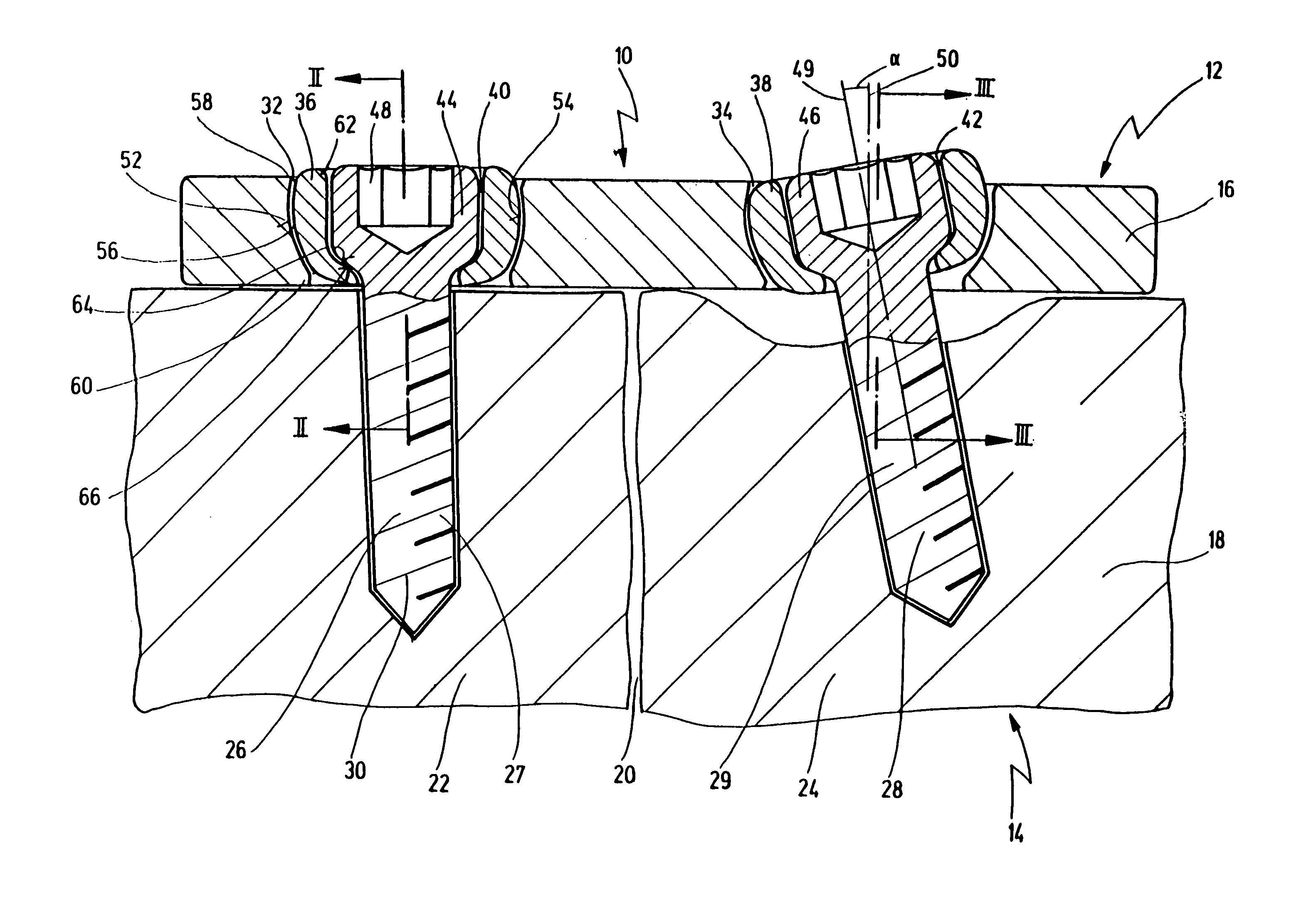
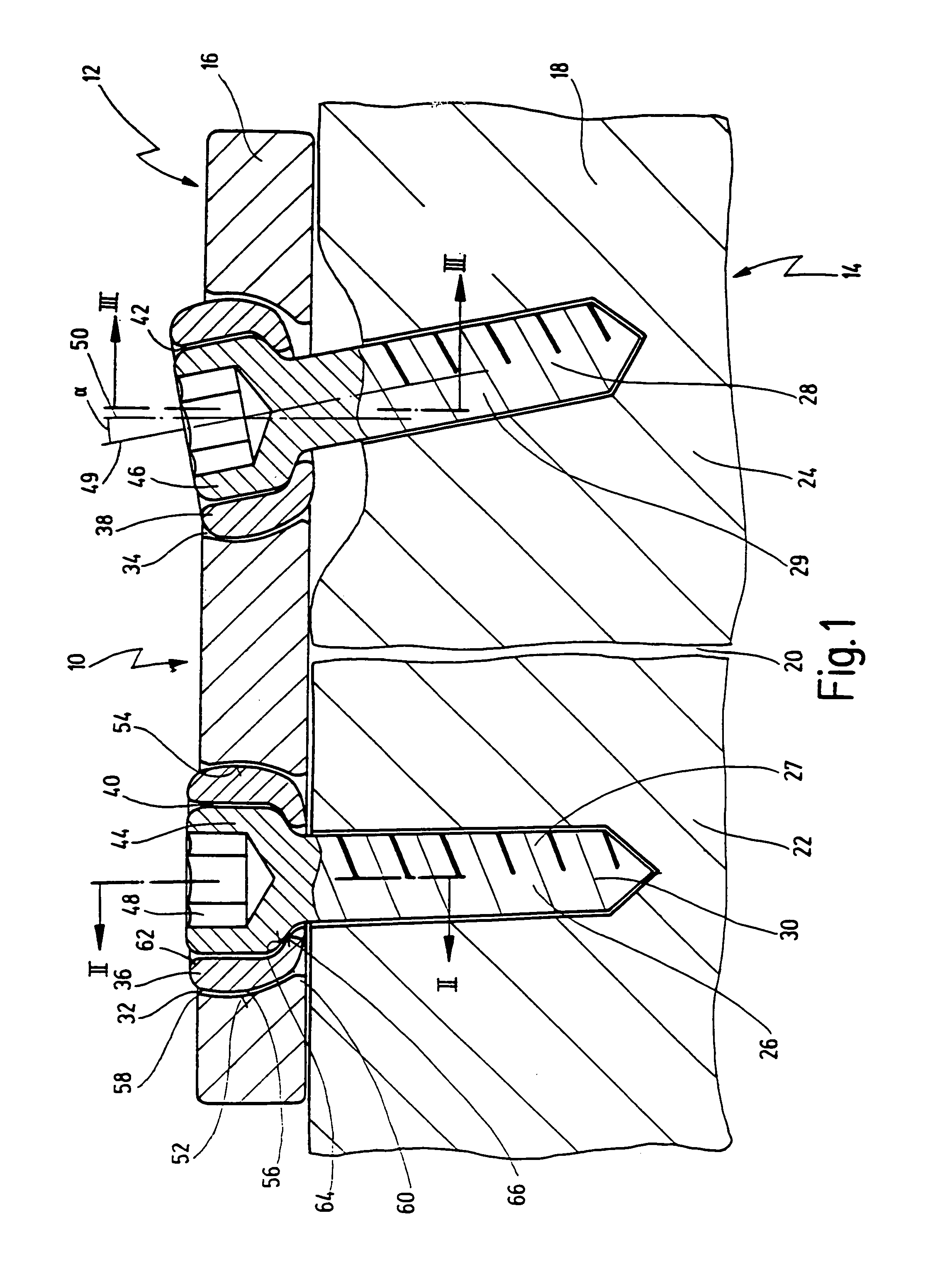
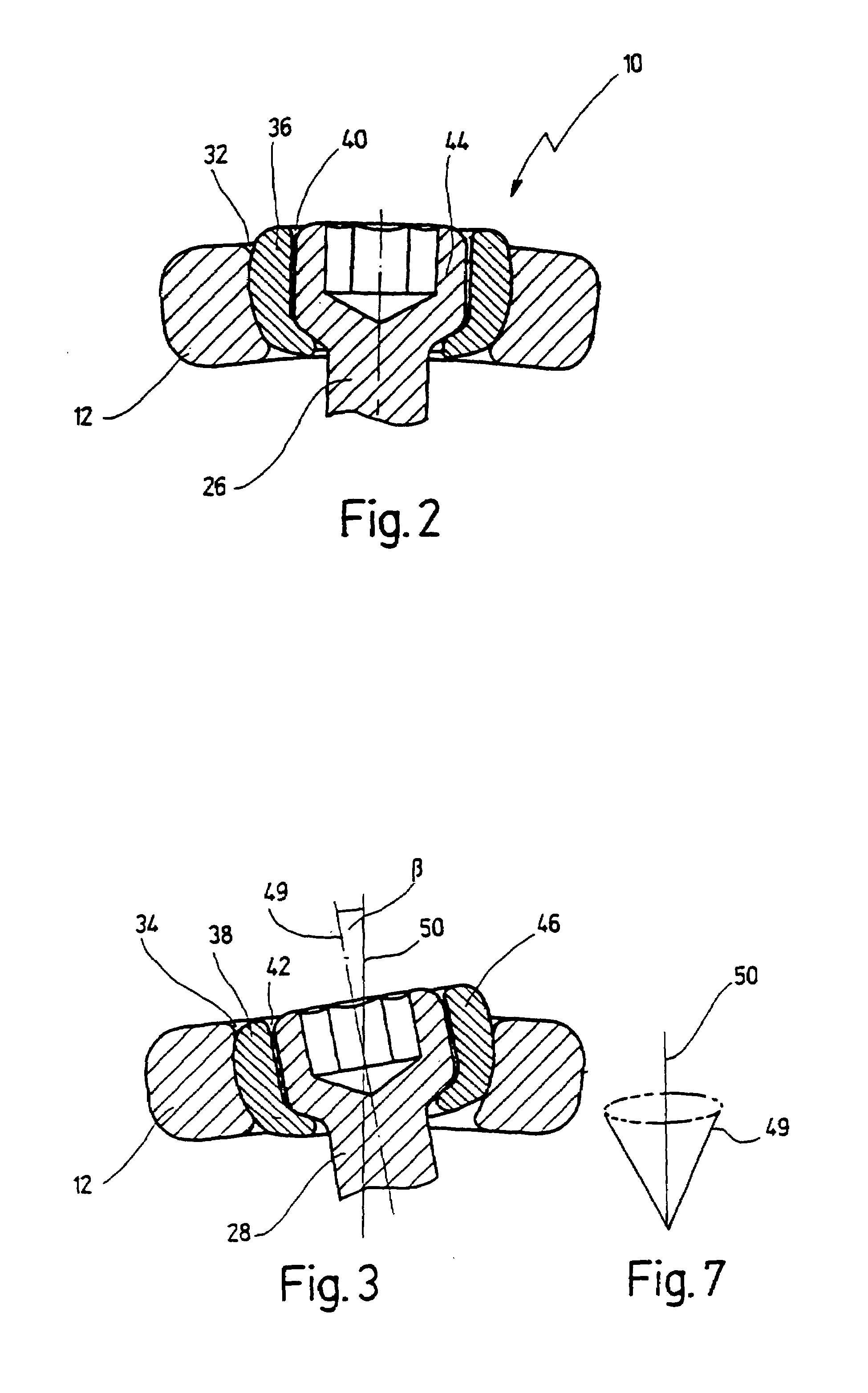
[0052]FIGS. 1 to 3 illustrate a fastening assembly designated with the numeral 10 for fastening a fixing element 12 to a substructure 14.

[0053]In the illustrated embodiment, the fixing element 12 is a brace 16 in the form of an approximately rectangular elongated plate, which is secured to a bone 18 having a fracture 20. Two bone parts 22, 24 separated by the fracture 20 are fixed to one another by the brace 16 to heal the fracture 20. The brace 16 is fastened with a first screw 26 and a second screw 28 to the bone part 22 and the bone part 24, respectively. The first screw 26 and the second screw 28 are bone screws, each having a threading 30 formed on a shaft 27, 29 of the screw 26, 28. The threading 30 cuts a corresponding thread in the bone parts 22, 24 when turning the screw 26 or 28.

[0054]The brace 16 includes a first bore 32 and a second bore 34, where a first bushing 36 is received in the first bore 32 and a second bushing 34 in the second bushing 38. The first bushing 36 co...


PUM


Abstract

A fastening assembly is provided for fastening a fixing element, for example a plate, a brace, an angle, a profile, an armature, a retainer or the like to a substructure by means of at least one screw, which can be passed through at least one bore in the fixing element and can be screwed into the substructure. A bushing is arranged in the bore to be able to be swiveled in arbitrary spacial direction. The screw is passed through the bushing. The bushing comprises a seat for at least partially receiving a head of the screw.

Description

CROSS REFERENCE TO PENDING APPLICATION[0001]This application is a continuation of pending International Application PCT / EP99 / 04973 filed on Jul. 14, 1999, which designates the United States.BACKGROUND OF THE INVENTION[0002]The invention relates to a fastening assembly for fastening a fixing element, for example a plate, brace, angle, profile, armature, retainer or the like, to a substructure by means of at least one screw which can be passed through at least one bore in the fixing element and can be screwed into the substructure.[0003]Numerous fastening assemblies of the mentioned type are known, which are provided for many different types of applications.[0004]For example, such fastening assemblies are used in the household, for example to mount objects on the wall or ceiling, such as lamps, shelves or the like. Normally, fixing elements in the form of wall fixtures, profiles or the like are provided for such objects which must then be secured to the wall or the ceiling by means of...

Claims


Application Information

Patent Timeline
IPC IPC(8): A61B17/56A61B17/80F16B5/02F16B43/02
CPCA61B17/8047F16B5/025F16B43/02
Inventor EBERLEIN, ROLANDWILBERG, LOTHAR
Owner BIEDERMANN TECH GMBH & CO KG
Why Eureka
Try Eureka