System and method for controlling an induction motor

a technology of induction motor and system, applied in the direction of electric controller, motor/generator/converter stopper, dynamo-electric converter control, etc., can solve the problems of not always cost-effective, longer circuit footprint, and more time for coasting to stop, so as to achieve faster deceleration, increase the back electromotive force, and increase the effect of regeneration

US7233125B2Active Publication Date: 2007-06-19STMICROELECTRONICS SRL
13 Cites 12 Cited by

Patent Information

Authority / Receiving Office
US · United States
Patent Type
Patents(United States)
Current Assignee / Owner
Publication Date
2007-06-19

Smart Images

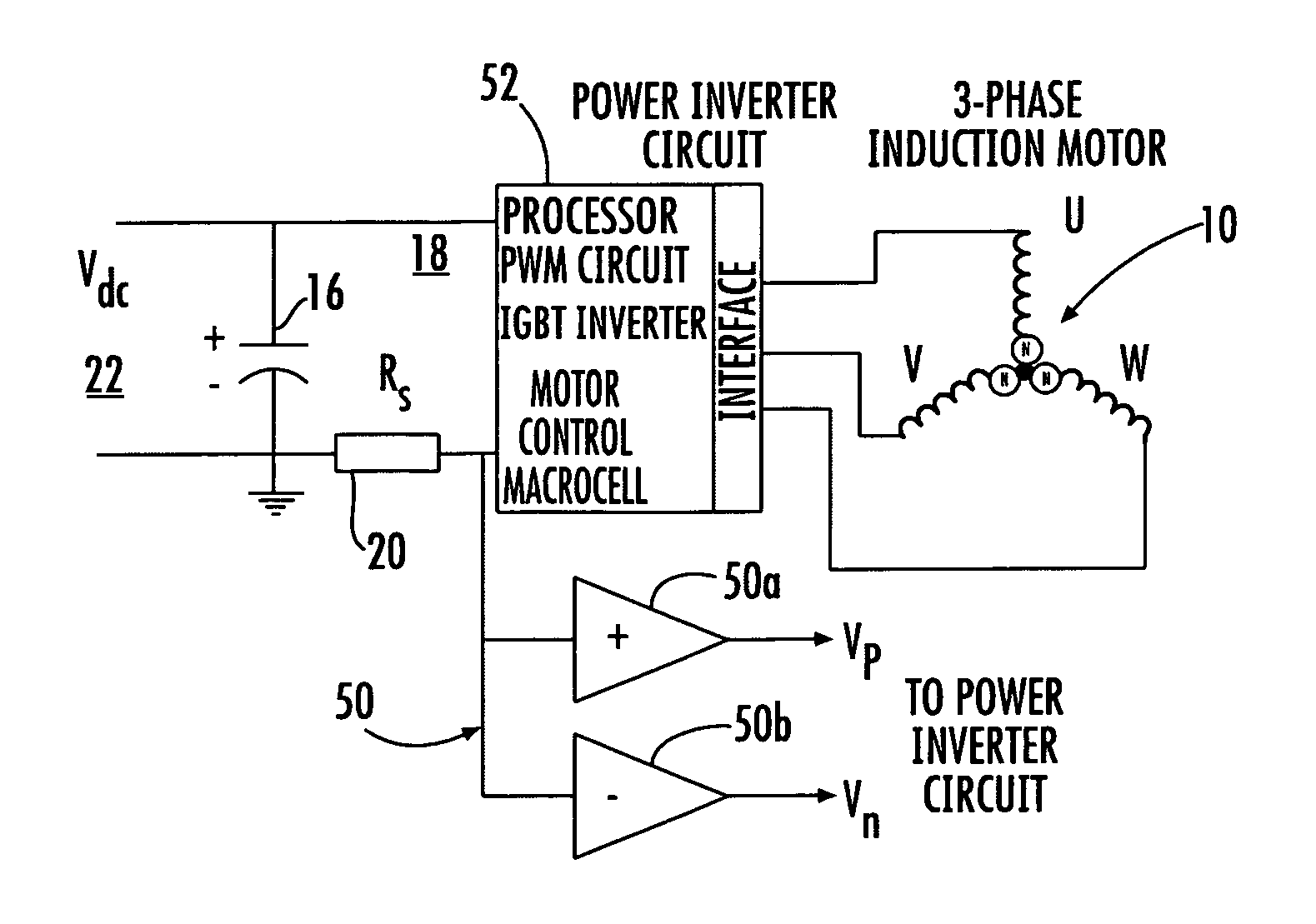
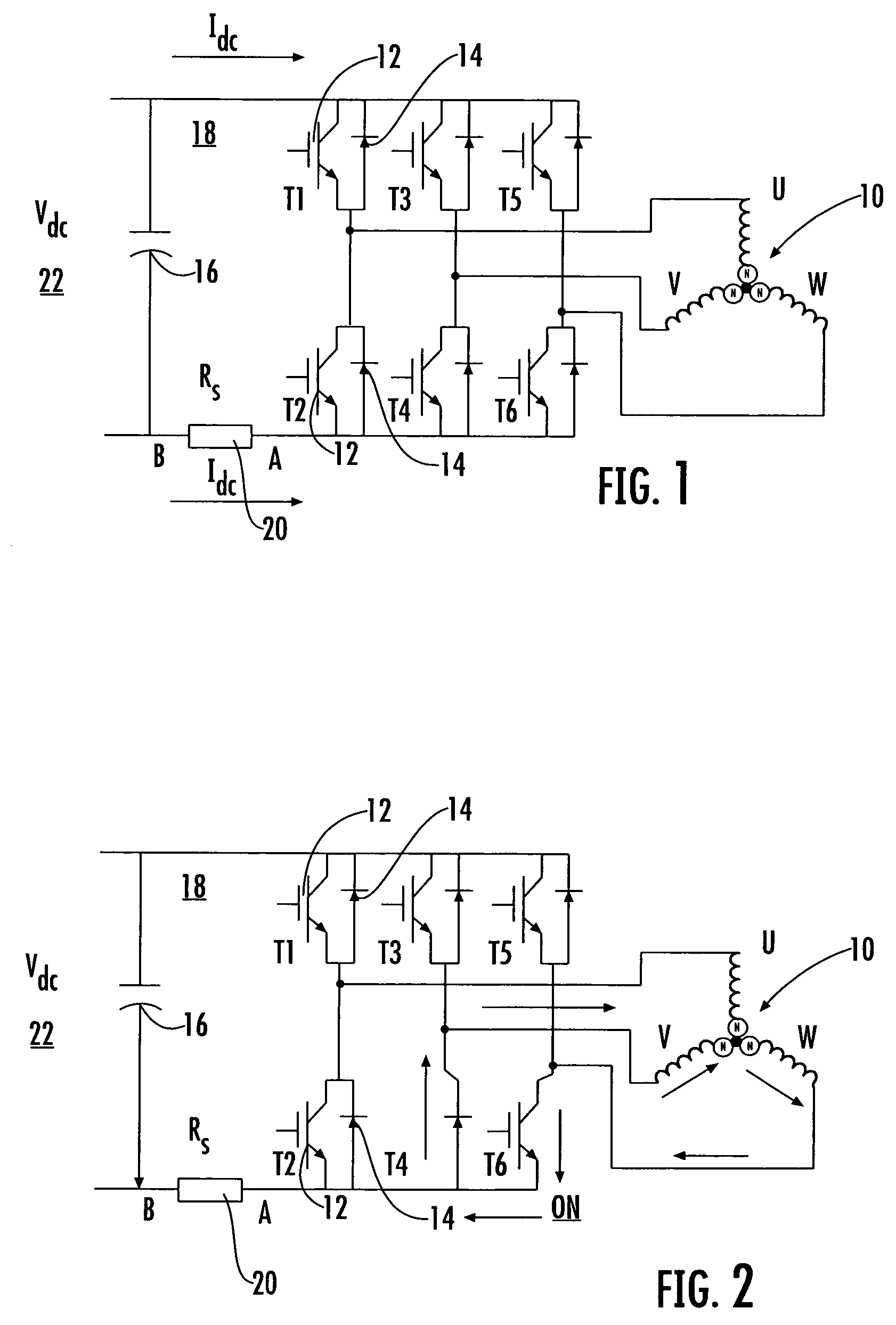
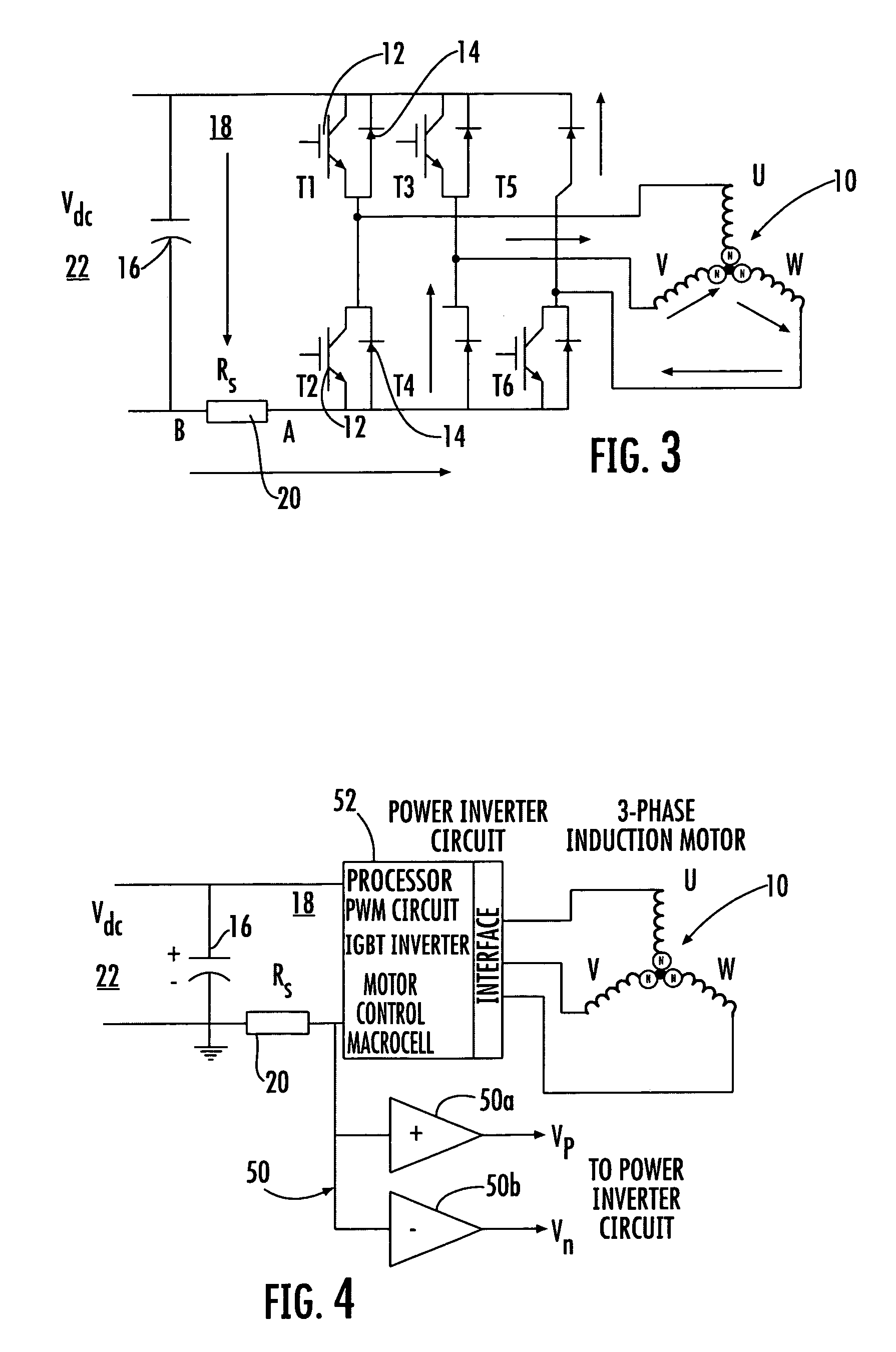
  • Figure 1
    Figure 1
  • Figure 2
    Figure 2
  • Figure 3
    Figure 3
Patent Text Reader

Abstract

A system controls an induction motor driven by a power inverter circuit. An operational amplifier circuit is operatively connected to the power inverter circuit and operative therewith for sensing DC current and controlling acceleration and deceleration of the induction motor. The operational amplifier circuit includes a first operational amplifier operative in a motoring mode to have a positive polarity output and remain substantially at zero during a regeneration mode. A second operational amplifier circuit is operative in a regeneration mode to have a negative polarity output and remain substantially at zero in a motoring mode.
Need to check novelty before this filing date? Find Prior Art

Description

FIELD OF THE INVENTION

[0001] The present invention relates to the field of induction motors, and more particularly, this invention relates to controlling voltage and current overload conditions during acceleration and deceleration of an induction motor.BACKGROUND OF THE INVENTION

[0002] In some prior art inverter fed induction motors, for example, used with some washing machines and similar motor applications, motor speed reversal is a normal occurrence. To avoid over current and voltage conditions during speed reversal, those skilled in the art have attempted to avoid over current and voltage conditions through different techniques.

[0003] For example, in one prior art technique, it is possible to disable all pulses to the inverter, and let the motor coast with its inertia to zero speed, and then restart in a reverse direction. A disadvantage to this approach is that coasting takes more time to stop. It is also possible to use vector control. Although this has been found to be an adequa...

Examples

Embodiment Construction

[0012]The present invention will now be described more fully hereinafter with reference to the accompanying drawings, in which preferred embodiments of the invention are shown. This invention may, however, be embodied in many different forms and should not be construed as limited to the embodiments set forth herein. Rather, these embodiments are provided so that this disclosure will be thorough and complete, and will fully convey the scope of the invention to those skilled in the art. Like numbers refer to like elements throughout.

[0013]In accordance with one non-limiting example of the invention, the system and method can typically eliminate over current and over voltage conditions that damage many power inverter stages during deceleration of induction motor drives. The system typically will have minimal hardware and software components. A microcontroller as a power inverter circuit with an insulated gate bipolar transistor (IGBT) is operative with a three-phase induction and perma...