
Flexible supply tube with weighting mechanism for use in spray bottles

a flexible supply tube and spray bottle technology, applied in the direction of hose connection, single-unit apparatus, liquid transfer device, etc., can solve the problems of tubing swelling or becoming slippery, no positioning of the container will allow, and spray bottles utilizing flexible tubes also suffer from certain drawbacks

Active Publication Date: 2007-07-10
SC JOHNSON & SON INC
View PDF61 Cites 18 Cited by
  • Summary
  • Abstract
  • Description
  • Claims
  • Application Information

AI Technical Summary

Benefits of technology

[0018]We prefer that the concave surfaces of the first and second retaining members be formed in a semi-cylindrical shape. In that way, the semi-cylindrical shapes may be positioned to couple the flexible tube along a length thereof. We also prefer that each of the first and second retaining members includes a pair of flanges positioned on opposite sides of the concave surface. The flanges extend out from each retaining member in a direction substantially perpendicular to the longitudinal axis of the semi-cylindrical concave surface and extend along the retaining member in a manner substantially parallel with the longit...

Problems solved by technology

Once the fluid level drops even farther, a user may find that no positioning of the container will allow the opening of the tube to reach the remaining fluid.
Nevertheless, spray bottles utilizing flexible tubes also suffer from certain drawbacks.
For instance, the fluids used in these containers are often cleaning solutions, which may have properties that cause the tubing to swell or become slippery.
Those conditions may cause the weight to slip off the tubing, if those elements are not properly secured to each other.
In addition, the weight may bang into the sides of the container causing unwanted noise and vibration.
Also, if the size of both the weighting mechanism and the tube or the fluid intake nozzle secured thereto are not properly proportioned, the system will not achieve maximum efficiency for reaching small amounts of fluid pooling in the corners of containers.

Method used


Image

  • Flexible supply tube with weighting mechanism for use in spray bottles
  • Flexible supply tube with weighting mechanism for use in spray bottles
  • Flexible supply tube with weighting mechanism for use in spray bottles

Examples


Embodiment Construction

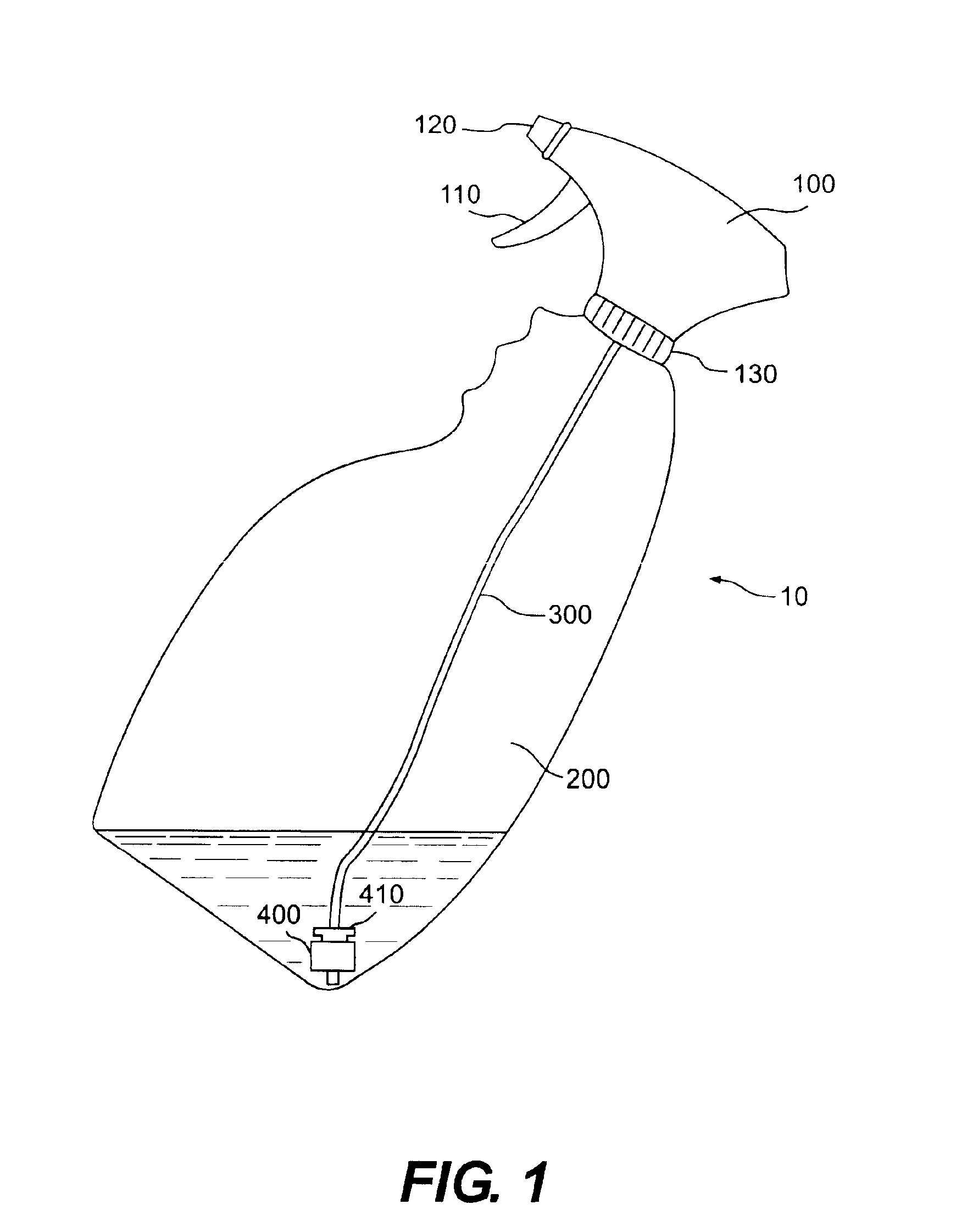
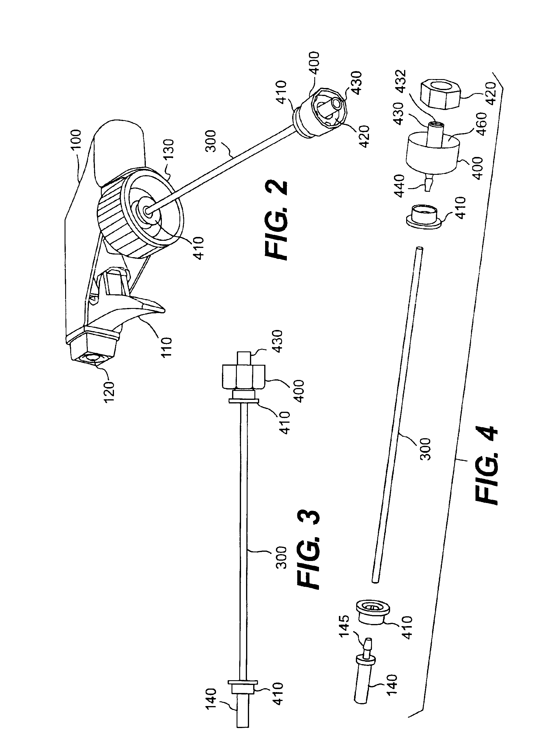
[0035]FIG. 1 shows a spray bottle 10 embodying one type of container to be used with our invention. Spray bottle 10 includes a pumping mechanism 100 and a container 200. While spray bottle 10 is the typical configuration in which the invention is to be embodied, other configurations may be substituted. Those various embodiments may include a wide range of containers from which fluid is to be drawn or pumped.

[0036]Pumping mechanism 100 includes a conventional pump operated by trigger 110. When trigger 110 is operated by a user, the pump draws fluid from inside the container and forces it through spray nozzle 120. Spray nozzle 120 creates a mist from the fluid pumped from the container. Pumping mechanism 100 is secured to container 200 by sealing member 130, which typically operates to threadingly engage container 200. These features, however, are known in the art and may be substituted with a number of alternative structures. In particular, spray bottle 10 may be a spray can operated...


PUM


Abstract

A spray bottle having a pump, flexible tubing, a housing and a retainer for clamping the tubing to the housing. The pump pumps fluid to be sprayed from inside the spray bottle. The flexible tubing is attached to the pump, extends into the spray bottle, and communicates fluid from inside the spray bottle to the pump. The housing is attached to a distal end of the flexible tubing and includes a head, a weight and a nozzle. The head projects into an opening in the distal end of the tubing. The weight is secured in the housing. The nozzle extends from an end of the housing opposing the end of the housing attached to the head. An opening in the nozzle and an opening in the head are in flow communication. The retainer encircles a portion of a periphery of the tubing and clamps the tubing against the head.

Description

[0001]This application claims benefit of 60 / 424,688 dated Nov. 8, 2002.BACKGROUND OF THE INVENTION[0002]1. Field of the Invention[0003]Our invention is directed to spray bottles and similar containers from which fluids are drawn through a tube or the like and dispensed. More specifically, our invention is directed to an improved system for removing fluid from containers through flexible tubing. In the system, a weighted member is secured to the distal end of the flexible tubing such that the weighted member pulls the distal end of the tubing toward the lowest point of the container, even when the container is shifted, rotated, tilted, inverted, and the like. More specifically, our invention is directed to novel designs, of weighting systems and clamps for securing such weighting systems to the flexible tubing.[0004]2. Description of the Related Art[0005]Traditional spray bottles include a container for holding a fluid, with a spraying mechanism secured to the opening of the containe...

Claims


Application Information

Patent Timeline
IPC IPC(8): B67D5/60B67D7/78B05B11/00F16L33/035
CPCB05B11/0059B05B15/006F16L33/035B05B15/33
Inventor HARRITY, KEVINBARTLETT, TIMOTHY R.DRISKELL, WILLIAM L.
Owner SC JOHNSON & SON INC
Learn More