Clamping and articulation element

a technology of articulation element and articulation cavity, which is applied in the direction of invalid friendly devices, prostheses, osteosynthesis devices, etc., can solve the problem of insertion of rod-shaped elements into the receiving cavity, and achieve the effect of simple manner

Active Publication Date: 2007-07-10
STRYKER EURO OPERATIONS HLDG LLC
View PDF20 Cites 91 Cited by
  • Summary
  • Abstract
  • Description
  • Claims
  • Application Information

AI Technical Summary

Benefits of technology

[0012]By equipping the single-piece clamping elements with functionally different first and second clamping jaws, two clamping elements can be placed on top of one another each with their first clamping jaws, to form an articulation element in a simple manner.

Problems solved by technology

One disadvantage of the known device is that the rod-shaped elements can be inserted into the receiving cavities only lengthwise from their ends.

Method used


Image

  • Clamping and articulation element
  • Clamping and articulation element
  • Clamping and articulation element

Examples


first embodiment

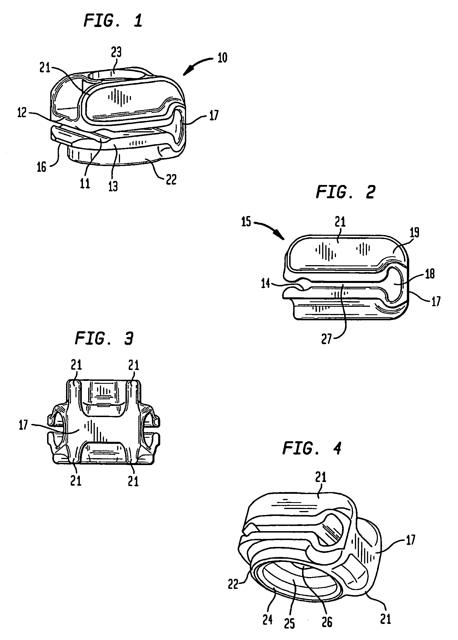
[0053]FIGS. 1 to 4 show a clamping element 10 per the invention. FIG. 1 shows a perspective view at an angle from the top. The clamping element 10 has two opposing cavities and one cavity 11 to receive clamping jaws 12 and 13 forming a rod-shaped element. On their free ends 15, clamping jaws 12 and 13 each have a transversely running grooves 14, which together clamp to form the cavity 11. At the free ends 15, the outer edges 16 of the side facing clamping jaws 12 and 13 are slanted to simplify the lateral insertion of a rod-shaped element. Across from the cavity 11 and the free ends 15, a hinge 17 is arranged, connecting clamping jaws 12 and 13 in a single piece. When the clamping element 10 is intended for a rod with 4 to 6 millimeters in diameter, the opening at the free ends has a diameter of, for instance, 2 millimeters in a resting position.

[0054]When clamping element 10 is made of synthetic material, hinge 17 is a thinned material section, followed by a recess 18 running later...

second embodiment

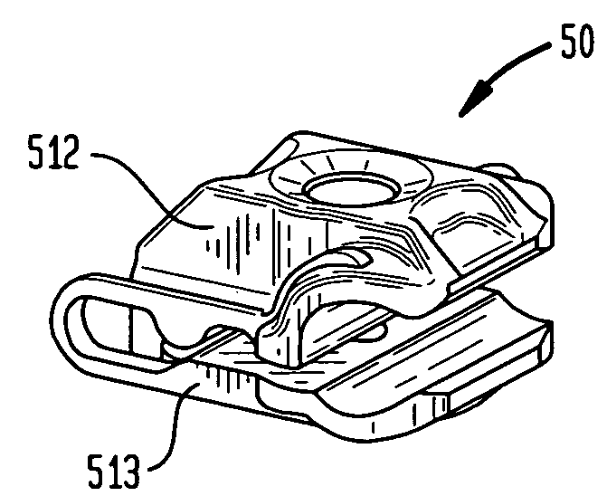
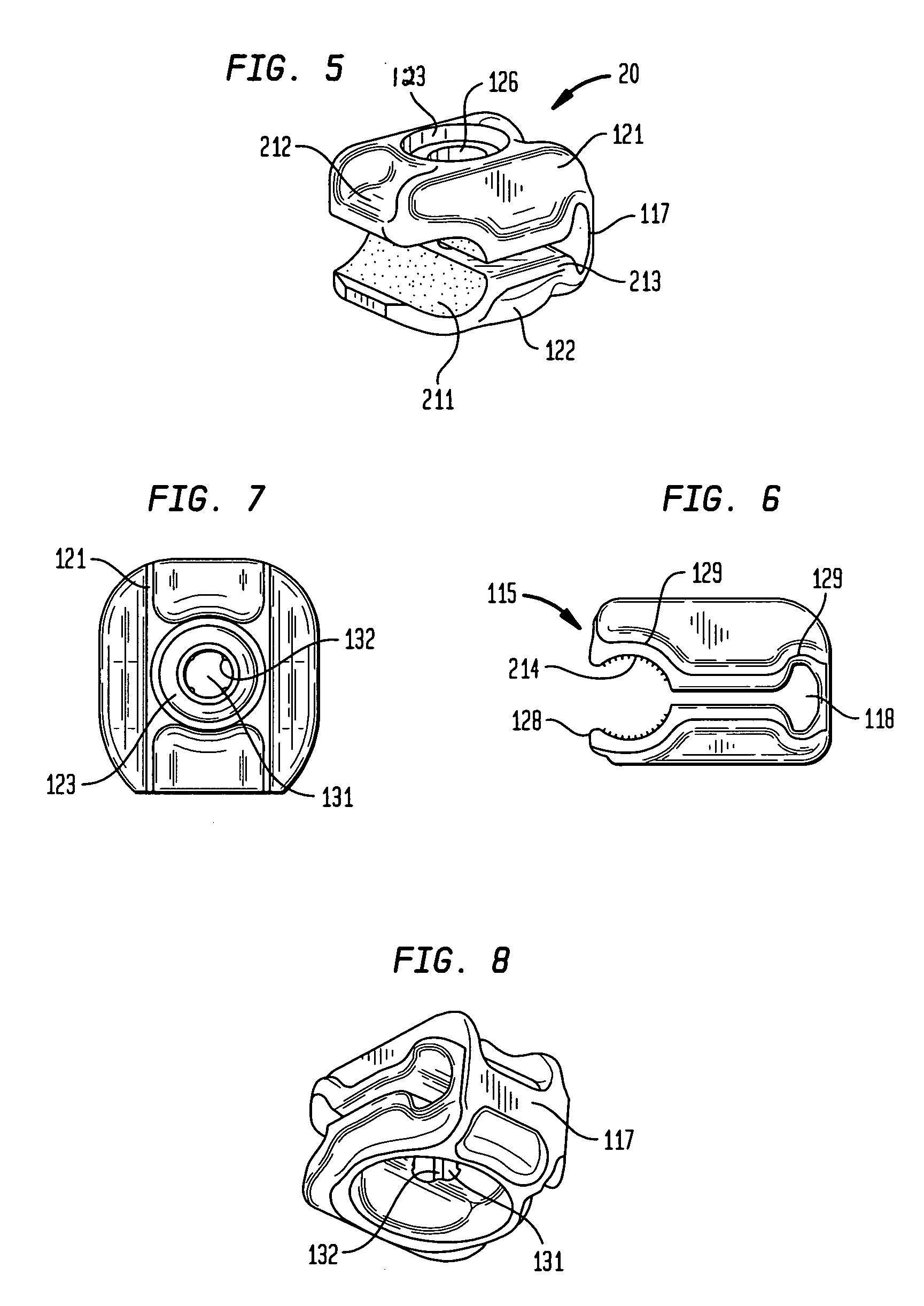
[0058]FIGS. 5 to 8 show a clamping element 20 according to the invention with a bore 126, cross ribs 121, hinge 117, ring flange 122 and jaw 212. The same characteristics are identified with reference numerals having the same last two digits. FIG. 5 shows a perspective view, at an angle from above. The only difference between the two clamping elements 10 and 20 per FIG. 1 and FIG. 5 is that clamping element 20 is intended to receive a rod-shaped element larger in diameter. This means that the grooves 214 are larger. The center axis of cavity 211, however, is still at the same height of slit 27. Here, the grooves 214 are so large that the free ends 115 form only a rounded area 128 to the outside, which simplifies a lateral insertion of rods. Like the fender 129 the groove 214, respectively the recess 118, is spanned to ensure the rigidity of the clamping element 20 (or 10). If the clamping element 20 is intended for a rod with a diameter of 12 millimeters, the opening at the free end...


PUM


Abstract

A one-piece clamping element has two opposing clamping jaws forming a laterally open cavity to receive a rod-shaped element. A hinge is located between the jaws, arranged opposite the cavity, and connecting the clamping jaws with one another and thus allowing them to be movable with respect to one another. Each clamping jaw has one bore, aligned flush with one another. One clamping jaw has a receptacle for an anti-rotation device. The receptacle makes it preferable—with the exception of an immediate tightening of the screw in this or another place of an external fixator clamping element used for the same patient—to use the clamping element only once and discarding it after use. Two identical clamping elements, with the possible exception of the size of the rod receptacle, can be placed on top of one another to form an articulation element.

Description

BACKGROUND OF THE INVENTION[0001]The invention pertains to a clamping element for the clamping of a rod-shaped element of an articulation, element particularly a clamping element of an articulation element for the stabilization of bone fractures. The invention also pertains to an articulation element with two clamping elements and with one at least two-piece locking device.[0002]EP 1 184 000 describes a single-piece clamping element with two opposing cavities and one laterally open cavity to receive a clamping jaw forming a rod-shaped element and a hinge, which is arranged opposite the cavity, connecting the clamping jaws so that they are movable on top of each other, with each clamping jaw having one bore each aligned flush with one another.[0003]This clamping element has the advantage that an articulation can be produced with two identical clamping elements arranged next to one another, inserting a connecting screw through the bore, which is screwed into an internally threaded nut...

Claims


Application Information

Patent Timeline
Patent Type & Authority Patents(United States)
IPC IPC(8): B25G3/36E04G7/00E04G7/14A61B17/64A61B19/00
CPCA61B17/645A61B17/6466Y10T403/7105Y10T24/44769A61B2019/4873A61B2090/0814
Inventor THOMKE, ROLANDBURGHERR, VINZENZLUTZ, CHRISTIANFANKHAUSER, DAMIANDRANSFELD, CLEMENSFISCHER, RENE
Owner STRYKER EURO OPERATIONS HLDG LLC
Why Eureka
Try Eureka