

Terminal support for a circuit breaker trip unit
a circuit breaker and terminal support technology, applied in the direction of circuit-breaking switches, switch terminals/connections, protective switch terminals/connections, etc., can solve problems such as cracking and breaking of circuit breaker bases
- Summary
- Abstract
- Description
- Claims
- Application Information
AI Technical Summary
Benefits of technology
Problems solved by technology
Method used
Image

Examples
Embodiment Construction
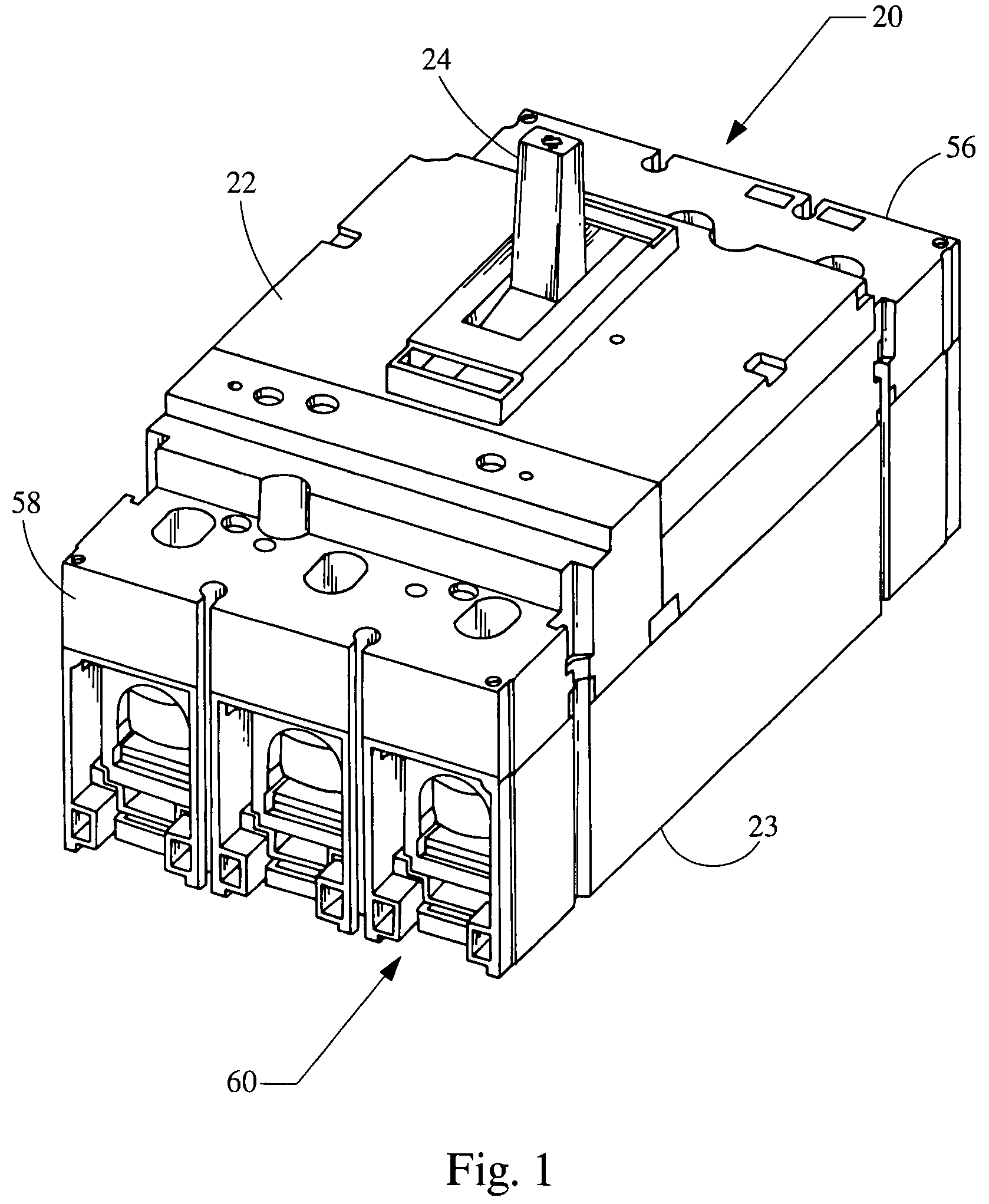
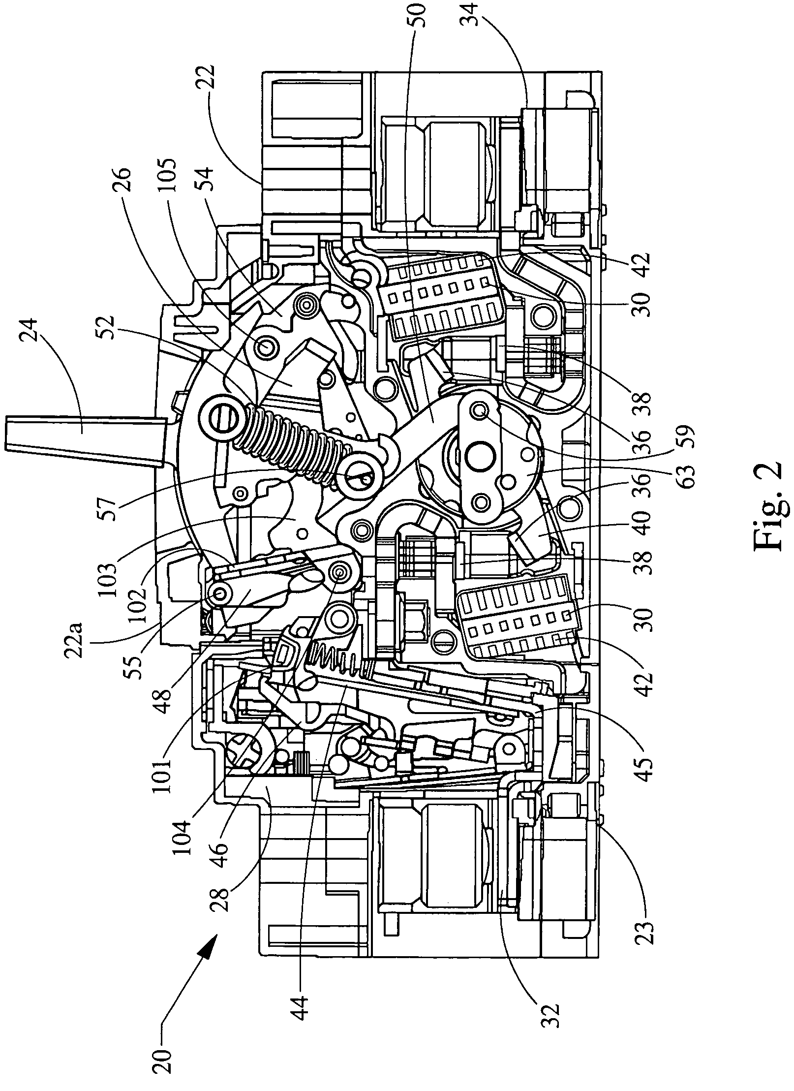
[0022]Referring now to the drawings, and initially to FIGS. 1 and 2, an electro-mechanical device such as a circuit breaker 20 will be described in general. The circuit breaker 20 generally includes a cover 22, a base 23, a handle 24, a switching mechanism 26, a trip assembly 28, and an arc-extinguishing assemblies 30.
[0023]In general, most components of the circuit breaker 20 are installed on the base 23 and secured therein after a cover 22 and finish cover 22a are attached to the base. The handle 24 protrudes through the cover 22a for manual resetting or switching on or off the circuit breaker 20. The handle 24 is also adapted to serve as a visual indication of one of several positions of the circuit breaker 20. One position of the circuit breaker 20 is an ON position. When the circuit breaker 20 is in the ON position, current flows unrestricted through the circuit breaker 20 and, therefore, through the electrical device or circuit that the circuit breaker is designed to protect. ...
PUM
 Abstract
Description
Claims
Application Information