
Variable pressure reusable sensor

a sensor and variable pressure technology, applied in the field of variable pressure reusable sensor, can solve the problems of reducing the patient's comfort, affecting the patient's comfort, etc., and achieve the effect of restricting the blood flow in the tissue site and uncomfortable for the patien

Active Publication Date: 2007-08-07
JPMORGAN CHASE BANK NA
View PDF105 Cites 850 Cited by
  • Summary
  • Abstract
  • Description
  • Claims
  • Application Information

AI Technical Summary

Problems solved by technology

A fixed pressure sensor poses several problems.
Sensor pressure set at time of manufacture cannot easily accommodate variations in tissue sites, patient ages or sizes, sensitivities to pressure, and perfusion characteristics.
Excess pressure restricts blood flow in the tissue site and is uncomfortable for the patient.
Insufficient pressure fails to keep the sensor attached to a particular tissue site.

Method used


Image

  • Variable pressure reusable sensor
  • Variable pressure reusable sensor
  • Variable pressure reusable sensor

Examples


Embodiment Construction

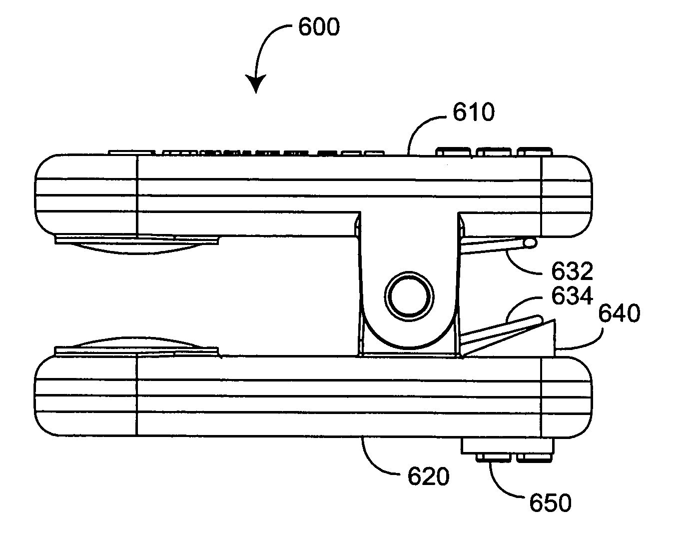
[0016]FIGS. 3A-B generally illustrate a variable pressure sensor clip 300 for a reusable sensor having opposing jaws 310 configured to clamp onto a tissue site placed between the jaws 310 with a pressure determined by a corresponding spring 320. For example, the jaws 310 may be pivotably connected by a hinge, with the spring 320 applying a spring force 332 on one section of the jaws 310 that is translated to a pressure 334 applied to the tissue site. The spring force 332 is determined by the tension characteristics of the spring 320, which is selectable when the sensor is manufactured, as described with respect to FIG. 3A, or adjustable, as described with respect to FIG. 3B.

[0017]As shown in FIG. 3A, one embodiment of the variable pressure sensor clip 300 utilizes a spring set 310 having various spring types 312. The spring 320 incorporated into a particular sensor 300 is a selected one of the spring types 312. Each spring type 312 is designed with different tension characteristics,...


PUM


Abstract

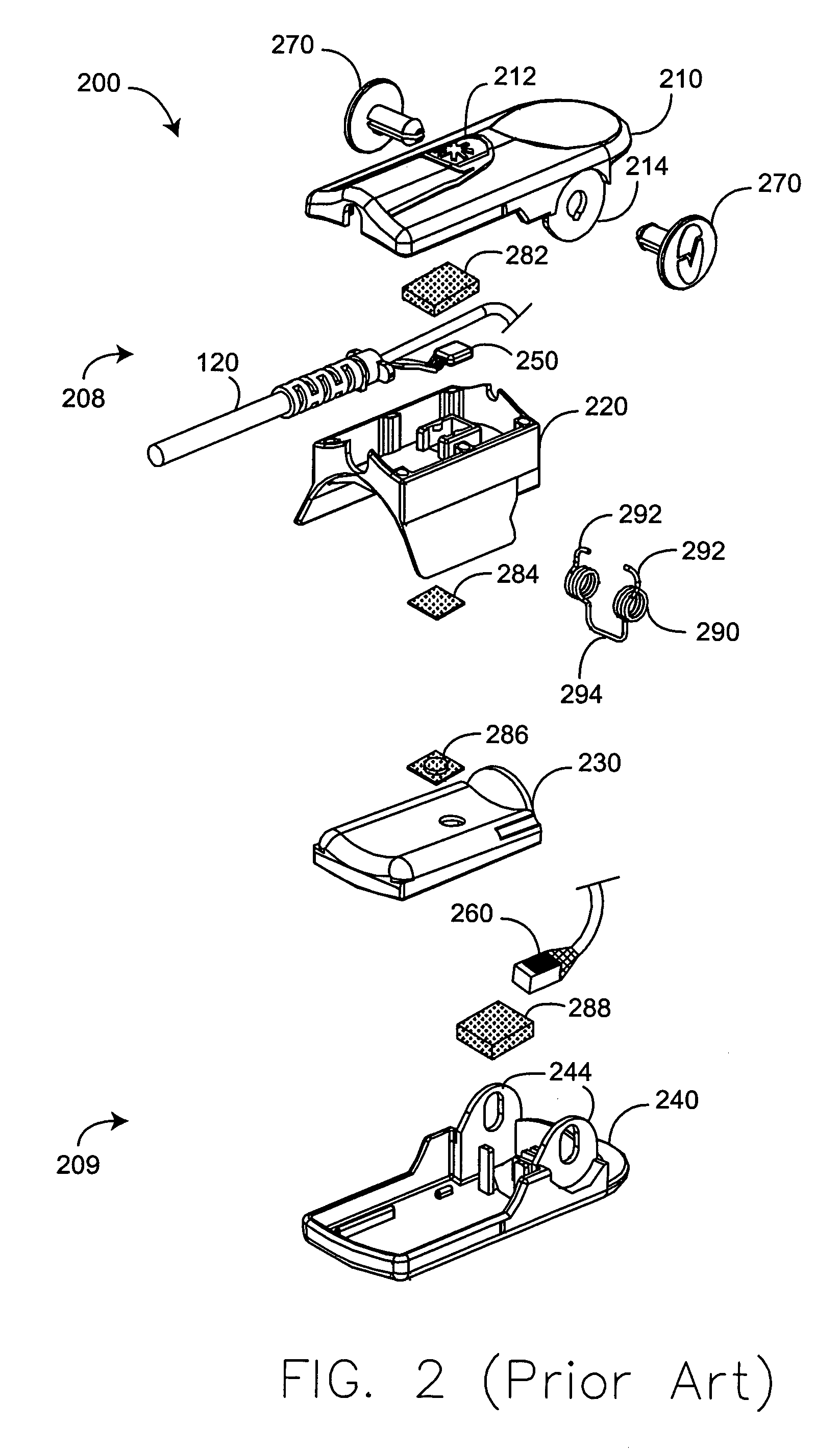
A variable pressure reusable sensor has a first jaw having a first hinge and an emitter and an opposing second jaw having a second hinge and a detector. A pin is disposed through the first and second hinges so as to rotatably attach the first and second jaws. The jaws are adapted to attach to a tissue site so that the emitter transmits optical radiation into the tissue site and the detector receives optical radiation after absorption by the tissue site. A spring having a plurality of legs is disposed around the pin and configured so that the legs apply force to the jaws. A tensioner is disposed proximate at least one of the jaws and configured to variably position at least one of the legs so as to adjust pressure exerted by the jaws on the tissue site.

Description

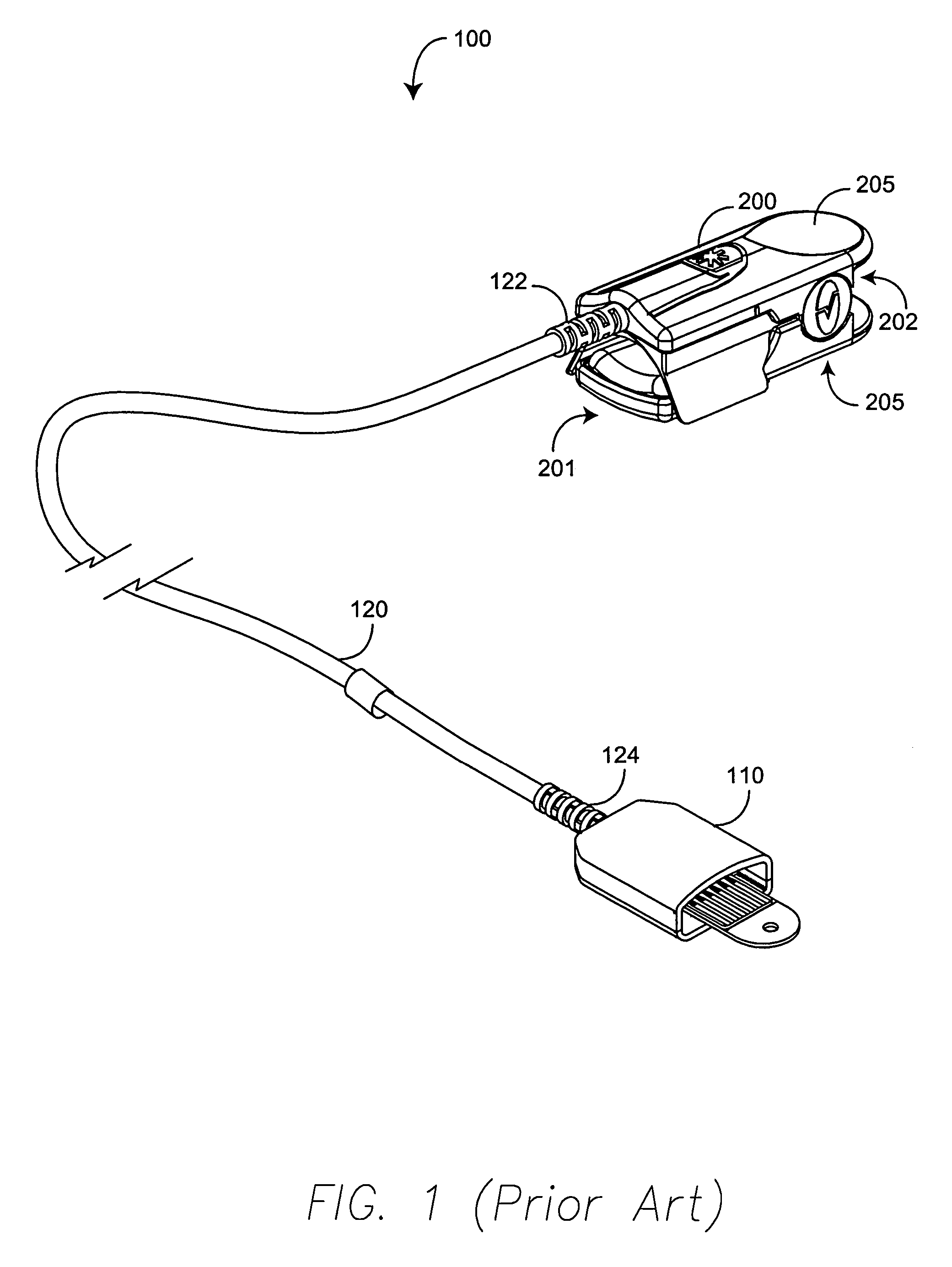
REFERENCE TO RELATED APPLICATION[0001]The present application claims priority benefit under 35 U.S.C. §119(e) from U.S. Provisional Application No. 60 / 510,879, filed Oct. 14, 2003, entitled “VARIABLE PRESSURE REUSABLE SENSOR,” which are incorporated herein by reference.BACKGROUND OF THE INVENTION[0002]Pulse oximeters perform a spectral analysis of the pulsatile component of arterial blood in order to determine oxygen saturation, the relative concentration of oxygenated hemoglobin to depleted hemoglobin. Pulse oximeters have gained rapid acceptance in a wide variety of medical applications, including surgical wards, intensive care units, general wards and home care by providing early detection of decreases in the arterial oxygen supply, reducing the risk of accidental death and injury. A pulse oximetry system consists of a sensor, a monitor and a patient cable providing electrical communication between the sensor and monitor. The sensor attaches to a patient tissue site and provides ...

Claims


Application Information

Patent Timeline
Patent Type & Authority Patents(United States)
IPC IPC(8): A61B5/00
CPCA61B5/14552A61B2562/146
Inventor SCHULZ, CHRISTIANAL-ALI, AMMARMASON, EUGENE
Owner JPMORGAN CHASE BANK NA
Learn More