
Miniature camera head

a camera head and miniature technology, applied in the field of miniature camera heads, can solve the problems of increasing the diameter of the endoscope, and achieve the effects of reducing the height of the turning mirror above the image sensor, reducing the diameter, and improving the quality of the endoscop

Active Publication Date: 2005-12-01
GYRUS ACMI INC (D B A OLYMPUS SURGICAL TECH AMERICA)
View PDF99 Cites 123 Cited by
  • Summary
  • Abstract
  • Description
  • Claims
  • Application Information

AI Technical Summary

Benefits of technology

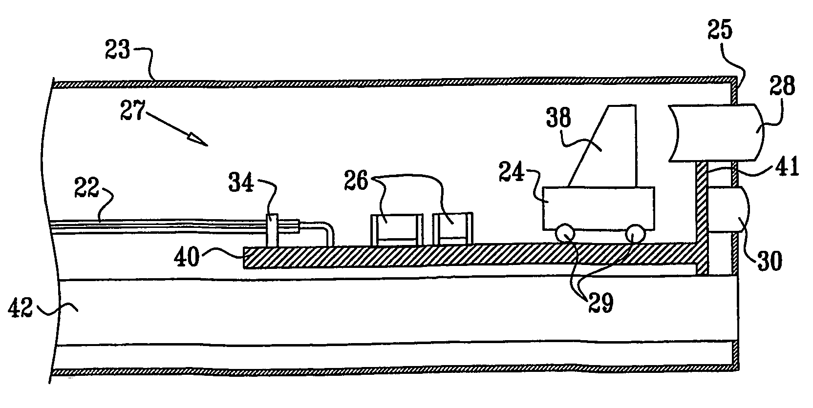
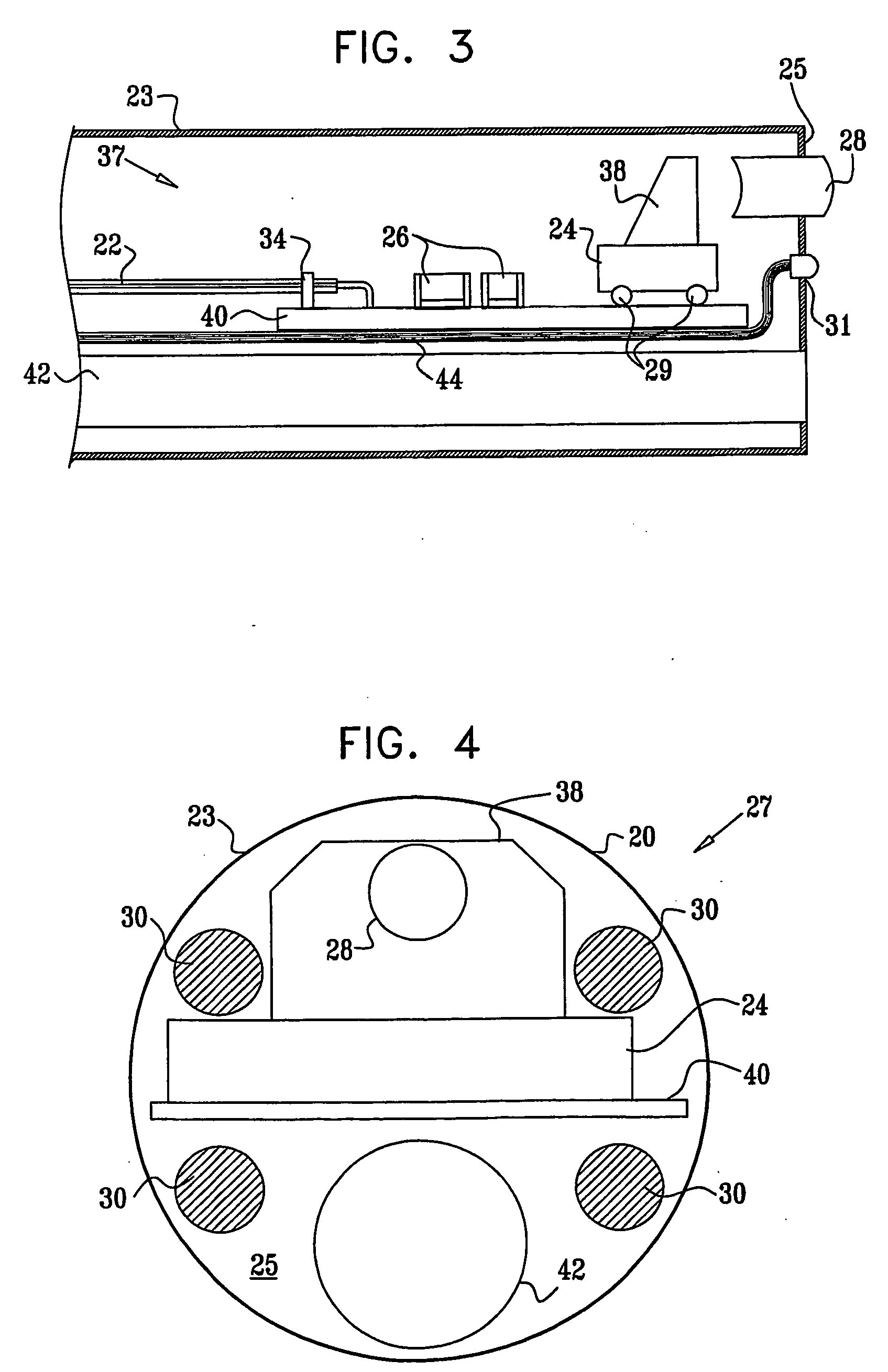
[0008] The camera head assembly is constructed and configured so as to reduce the radial dimensions of the assembly (measured in a plane perpendicular to the optical axis) to a substantially smaller size than has been achieved in comparable assemblies known in the art. Typically, the assembly is capable of fitting inside a tube, such as the insertion tube of an endoscope, whose diameter is smaller than the diagonal dimension of the image sensor. The reduction of diameter is achieved, inter alia, by a novel optical design, which allows the height of the turning mirror above the image sensor to be reduced in comparison to designs known in the art in which the sensor is oriented parallel to the optical axis. Additionally or alternatively, novel methods for mounting the image sensor chip within the camera head are used to reduce the diameter still further.

Problems solved by technology

These two objectives are often mutually contradictory, since increasing the resolution of the sensor generally requires increasing its size, which leads to increasing the diameter of the endoscope.

Method used


Image

  • Miniature camera head
  • Miniature camera head
  • Miniature camera head

Examples


Embodiment Construction

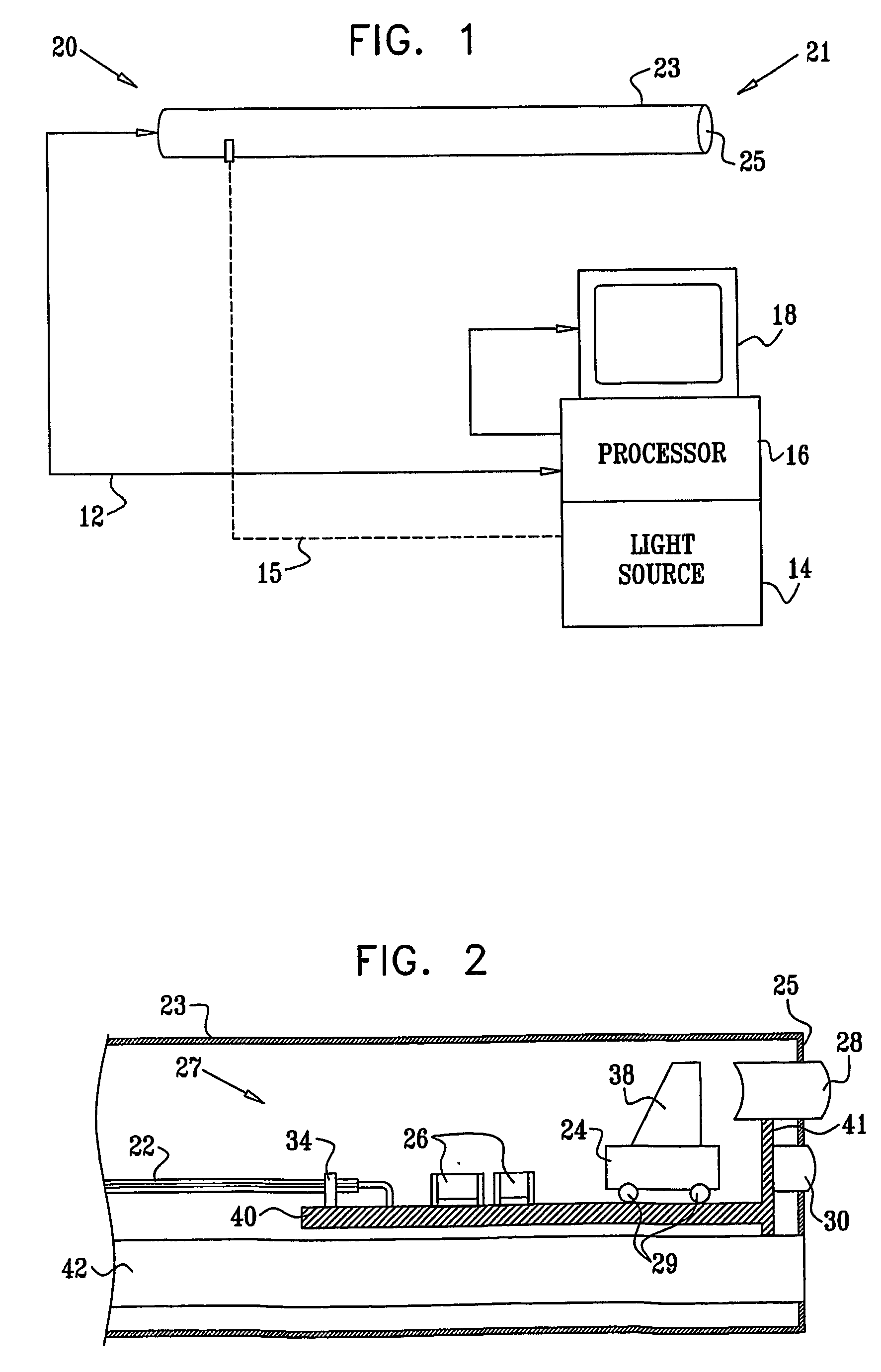
[0091] Reference is now made to FIG. 1, which is a block diagram that schematically illustrates an endoscopic imaging system 20, in accordance with an embodiment of the present invention. System 20 comprises an endoscope 21, which is connected by a cable 12 to a processing unit 16. The endoscope comprises an insertion tube 23, containing a miniature camera head at its distal end 25, as shown and described hereinbelow. Typically, the endoscope also contains an internal light source, for illuminating the area adjacent to the distal end of the endoscope, which is imaged by the camera head. Alternatively or additionally, an external light source 14 may be used to provide illumination via a fiberoptic bundle 15 to a light guide within endoscope 21. The external light source may alternatively be coupled optically to the distal end of the endoscope via one or more liquid-filled light guides. Light source 14 typically comprises one or more solid-state emitters, such as LEDs, as described be...


PUM


Abstract

An electronic imaging device (27) includes an optical objective (28) for collecting optical radiation from an object, the objective having an optical axis, and an image sensor (24), including a matrix of optical detectors arranged in a plane that is substantially non-perpendicular to the optical axis, the image sensor having a lateral dimension in the plane. A turning mirror (38) has an optical surface that is positioned so as to reflect the radiation collected by the objective in order to form a focused image in the plane of the image sensor, while a maximum distance from the optical surface to the plane of the image sensor is substantially less than the lateral dimension of the image sensor.

Description

CROSS-REFERENCE TO RELATED APPLICATIONS [0001] This application claims the benefit of U.S. Provisional Patent Application No. 60 / 381,478, filed May 16, 2002, whose disclosure is incorporated herein by reference.FIELD OF THE INVENTION [0002] The present invention relates generally to electronic imaging systems, and particularly to miniature camera heads and associated illumination devices, especially for use in endoscopy. BACKGROUND OF THE INVENTION [0003] Miniature, remote-head cameras are commonly used in endoscopy and other areas of minimally-invasive surgery. A solid-state imaging sensor is fixed in the distal end of an endoscope, along with suitable imaging optics and an illumination source, in order to capture images within body cavities and passageways. In general it is desirable to reduce the endoscope diameter and at the same time to improve the image quality obtained from the distal-end camera head. These two objectives are often mutually contradictory, since increasing the...

Claims


Application Information

Patent Timeline
Patent Type & Authority Applications(United States)
IPC IPC(8): G02B23/26A61B1/00A61B1/04A61B1/05G02B13/10G02B17/08H04N25/00
CPCA61B1/00096A61B1/00193A61B1/05A61B1/051A61B1/0676A61B1/07H04N5/2253H04N5/2254H04N5/2256H04N2005/2255A61B1/0684G02B13/0065G02B23/2423H04N23/555H04N23/56H04N23/54H04N23/55
Inventor BLUMZVIG, ARIEZARETSKY, ALEXADLER, DOROND'AMELIO, FRANK
Owner GYRUS ACMI INC (D B A OLYMPUS SURGICAL TECH AMERICA)
Learn More