One-way clutch fixing structure

a one-way clutch and fixing structure technology, which is applied in the direction of interengaging clutches, couplings, bearing unit rigid supports, etc., can solve the problems of large forming cost, difficult control of the outer diameter and inability to control the dimension of the outer ring outer diameter, etc., to achieve positive prevention of creep, the effect of general equal or lower overall cost and low cos

Inactive Publication Date: 2007-08-21
JTEKT CORP
View PDF10 Cites 4 Cited by
  • Summary
  • Abstract
  • Description
  • Claims
  • Application Information

AI Technical Summary

Benefits of technology

[0023]In the present invention, a creep is positively prevented, and it is substantially unnecessary to control the dimension of the outer diameter of the outer ring, and therefore the control of the dimensions of the inner and outer rings so as to adjust a space therebetween can be effected quite easily, and the overall cost can be made generally equal to or lower than that of the related construction. In the case of using the resin-molded housing, the outer ring of the one-way clutch can be integrally connected to the housing by insert molding while keeping the cost to a low level. And besides, the hole is formed in that portion of the outer ring corresponding to the one-way clutch track surface, and therefore the overall strength of the rolling bearing-integrated one-way clutch (to which the invention is applied) will hardly be reduced.

Problems solved by technology

Incidentally, in the case where the housing is formed, for example, by press working, and its dimensional accuracy and shape accuracy are low, it is difficult to control the dimension of the outer diameter of the outer ring so as to fit the outer ring in the housing by the predetermined interference fit.
In the above related creep prevention technique in which the stop ring is mounted in the eccentric groove formed in the outer ring, a considerable cost is required for forming the eccentric groove in the outer ring, and besides it is difficult to completely eliminate a possibility that a slip develops between the stop ring and the outer ring and also between the stop ring and the housing with respect to the relation between the depth of the eccentric groove and the dimension of the inner diameter of a housing hole, since a resilient force of the stop ring is utilized.
Therefore, it is difficult to completely solve the problem that creep develops between the outer ring and the housing.
In the case of using such a resin-molded housing, a certain degree of effect can be expected by the use of the above related technique, but there still remains the problem that the cost for forming the eccentric groove in the outer ring increases considerably.
In the insert molding method, however, it is substantially impossible to integrally connect the outer ring to the housing by interference fit, and it is expected that there arises a problem that the creep phenomenon (in which the two rotates relative to each other) is liable to develop due for example to the difference in thermal expansion between the two.

Method used


Image

  • One-way clutch fixing structure
  • One-way clutch fixing structure
  • One-way clutch fixing structure

Examples


first embodiment

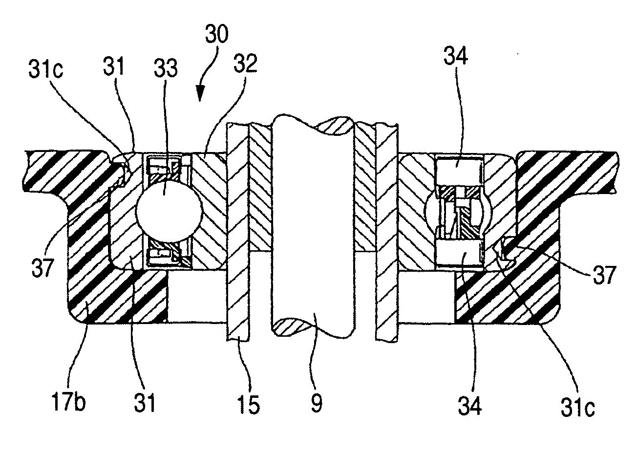
[0047]In this first embodiment described above, the holes 31c are formed in the outer ring 31, and the resin flows into the holes 31c during the insert molding. Instead of this method, there can be used a method (shown in FIG. 6) in which pins 31d are inserted respectively in holes 31c formed in the outer ring 31, and the outer ring 31, having the pins 31d inserted in the respective holes 31c, is integrally connected to the lower housing 17b by insert molding when this lower housing 17b is molded, so that the pins 31d are embedded in the resin. With this method, similar effects as described above can be achieved. In this case, when the pins 31d of a hollow construction are used as in the illustrated example, the resin intrudes into the interior of each pin 31d, and therefore the relative rotation can be prevented even when a large torque is applied.

[0048]In the above first embodiment, although the two holes 31c or the two pins 31d are provided at the outer ring 31, one or more than ...

second embodiment

[0055]In this second embodiment of the invention, even if the outer diameter of the outer ring 112 and the inner diameter of the fitting hole 131 in the housing 103 are so determined that the outer ring 112 is suitably loosely fitted in the fitting hole 131, the outer ring 112 and the housing 131 will not rotate relative to each other, thereby positively preventing a creep from occurring, since the pins 102, fixed to the outer ring 112, are fitted respectively in the grooves 132a and 132b formed in the inner peripheral surface of the fitting hole 131. And besides, the holes 112c through which the pins 102 are fixed to the outer ring 112 are disposed at the portion corresponding to the one-way clutch track surfaces 112b, respectively. Therefore, the provision of the holes 112c will not adversely affect the strength of a reduced-thickness portion of the outer ring 112 at which the bearing track surface 112a is formed and on which a radial load always acts. Therefore, the overall stren...


PUM


Abstract

Holes of a predetermined depth are formed in an outer peripheral surface of an outer ring. The outer ring is integrally connected to a housing by insert molding, so that a resin, forming the housing, is received in the holes. Alternatively, pins are fixedly inserted respectively in the holes, and are fitted respectively in grooves, notches or through holes formed in the housing. With this construction, a creep is positively prevented without the need for providing an interference fit between the housing and the outer ring.

Description

BACKGROUND OF THE INVENTION[0001]This invention relates to a structure of fixing a one-way clutch to a housing. The invention can also be applied to a so-called rolling bearing-integrated one-way clutch in which a one-way clutch and a rolling bearing have common outer or inner rings.[0002]Generally, a one-way clutch includes a plurality of wedge elements (such as sprags or rollers), and an urging member for urging these wedge elements in a predetermined direction (locking direction). Sprags, rollers or the like are used as the wedge elements, and when the inner and outer rings rotate relative to each other, a torque is transmitted in one direction only by the interaction between the shape of the wedge elements and the shape of a space between the inner and outer rings, and the inner and outer rings idle relative to each other in the other direction. There is also known a so-called rolling bearing-integrated one-way clutch in which the outer ring and inner ring of such a one-way clut...

Claims


Application Information

Patent Timeline
Patent Type & Authority Patents(United States)
IPC IPC(8): F16D41/06D06F37/30F16D41/067F16D41/07
CPCF16D41/067F16D2300/12F16C35/067F16C41/001F16C19/06F16C33/3806F16D41/07F16D41/06
Inventor IKEDA, TETSUO
Owner JTEKT CORP
Why Eureka
Try Eureka