Antenna mounting device

a technology for mounting devices and antennas, which is applied in the direction of antennas, antenna details, and antenna adaptation in movable bodies, etc., can solve the problems that the typical vehicle roof mount antenna cannot be easily secured or attached to the supporting facilities, particularly the vehicles by themselves, and achieves the effect of easy and convenient mounting of antenna members

Inactive Publication Date: 2007-08-21
JOYMAX ELECTRONICS CO LTD
View PDF6 Cites 11 Cited by
  • Summary
  • Abstract
  • Description
  • Claims
  • Application Information

AI Technical Summary

Benefits of technology

[0009]The primary objective of the present invention is to provide an antenna mounting device including a structure for easily and readily attaching an antenna member to various supporting facilities, such as wall members, window glasses, vehicle roofs, etc.
[0011]The base casing includes at least one rib extended outwardly from the outer peripheral fence, and the housing includes at least one groove formed therein for receiving the rib of the base casing and for anchoring and positioning the base casing to the housing and for preventing the base casing from being rotated relative to the housing.
[0013]The ring member includes a bore, the cap includes a shank engaged into the bore of the ring member and includes a peripheral flange extended radially and outwardly from the shank and engaged with the ring member for anchoring the cap to the ring member and for allowing the cap and the ring member to be moved up and down in concert with each other.

Problems solved by technology

However, the antenna base includes a power supply cord that is required to be engaged through the typical vehicle roof; i.e., the typical vehicle roof is required to be drilled with a hole for receiving or engaging the power supply cord, such that the typical vehicle roof mount antenna may not be easily secured or attached onto the supporting facilities, particularly the vehicles by themselves.

Method used


Image

  • Antenna mounting device
  • Antenna mounting device
  • Antenna mounting device

Examples


Embodiment Construction

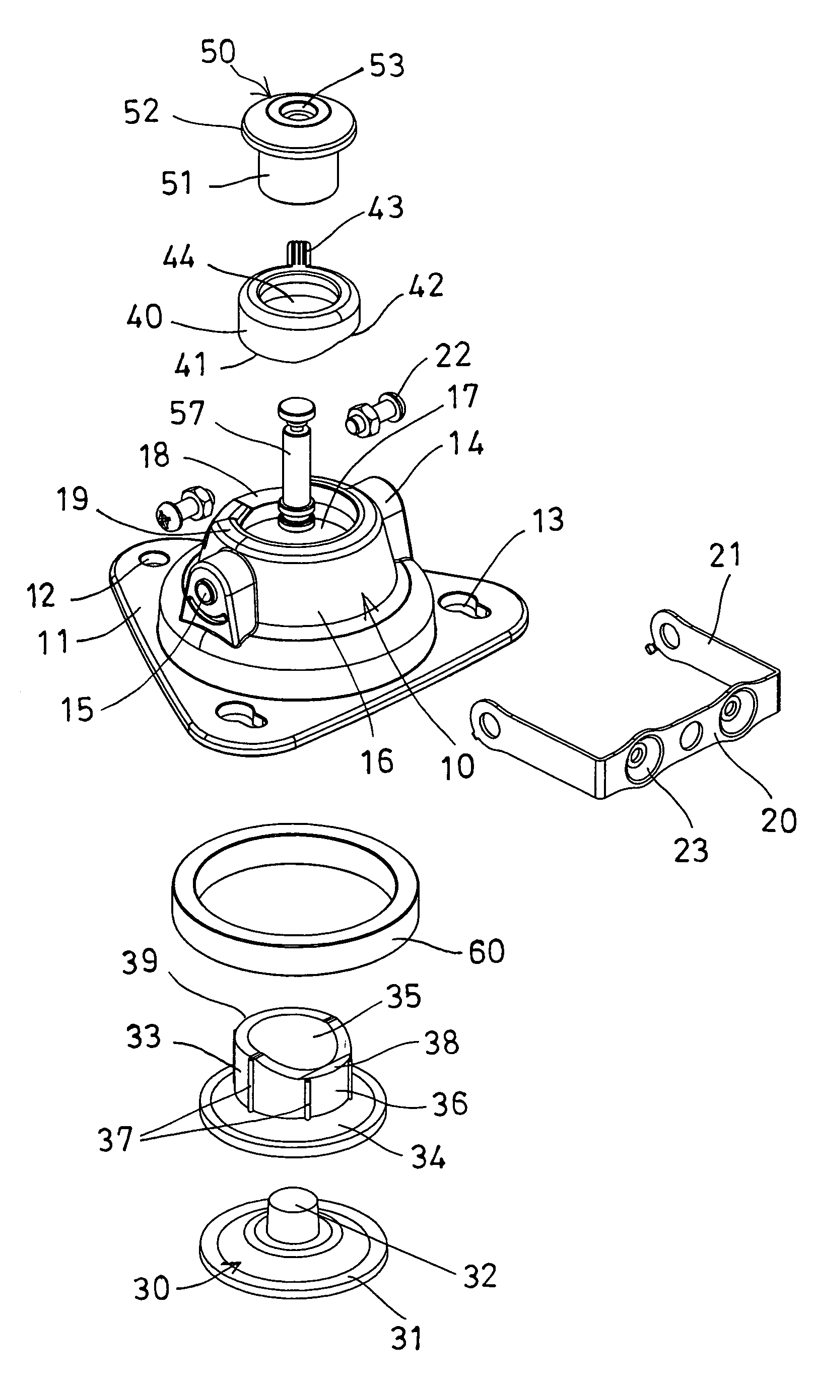
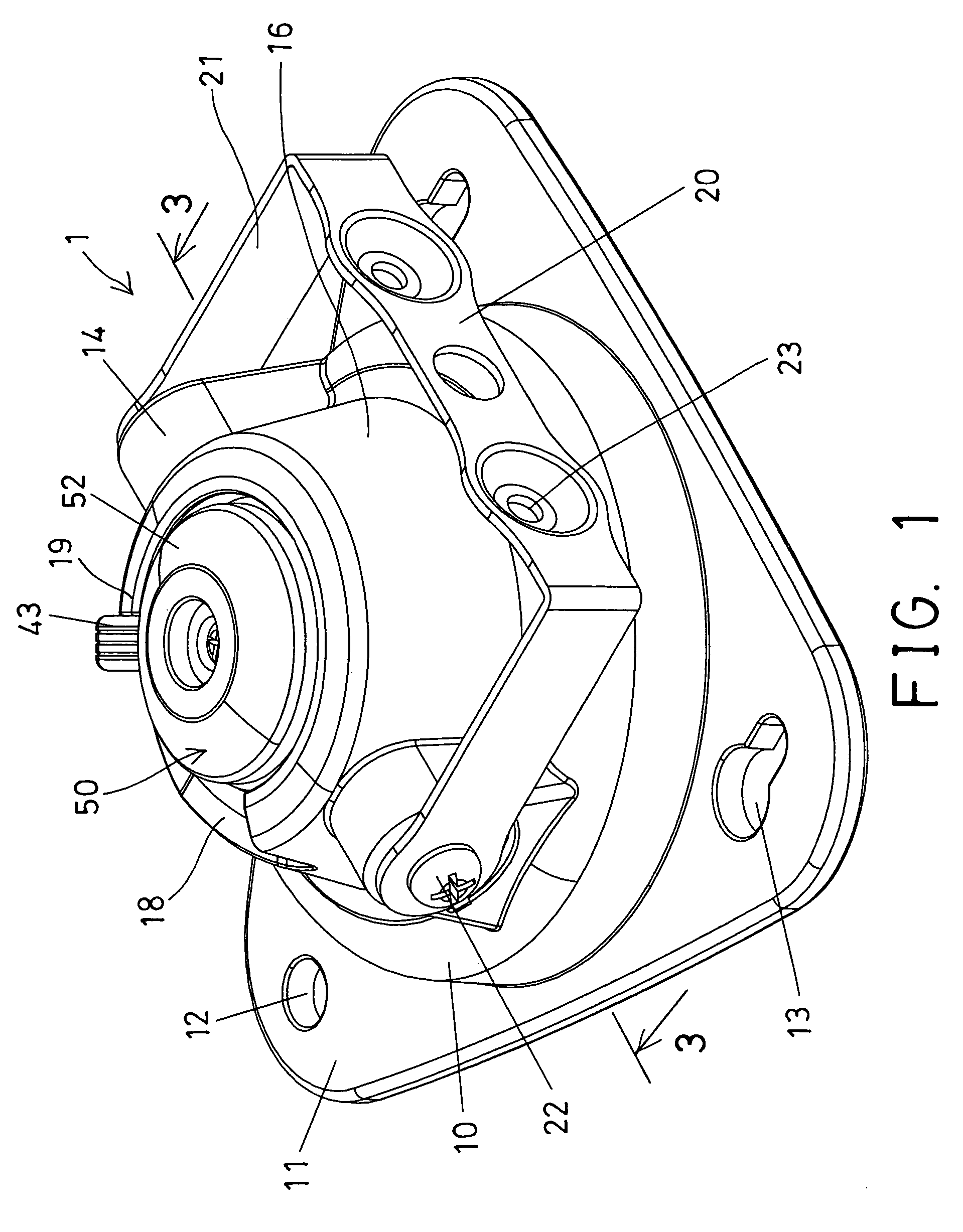
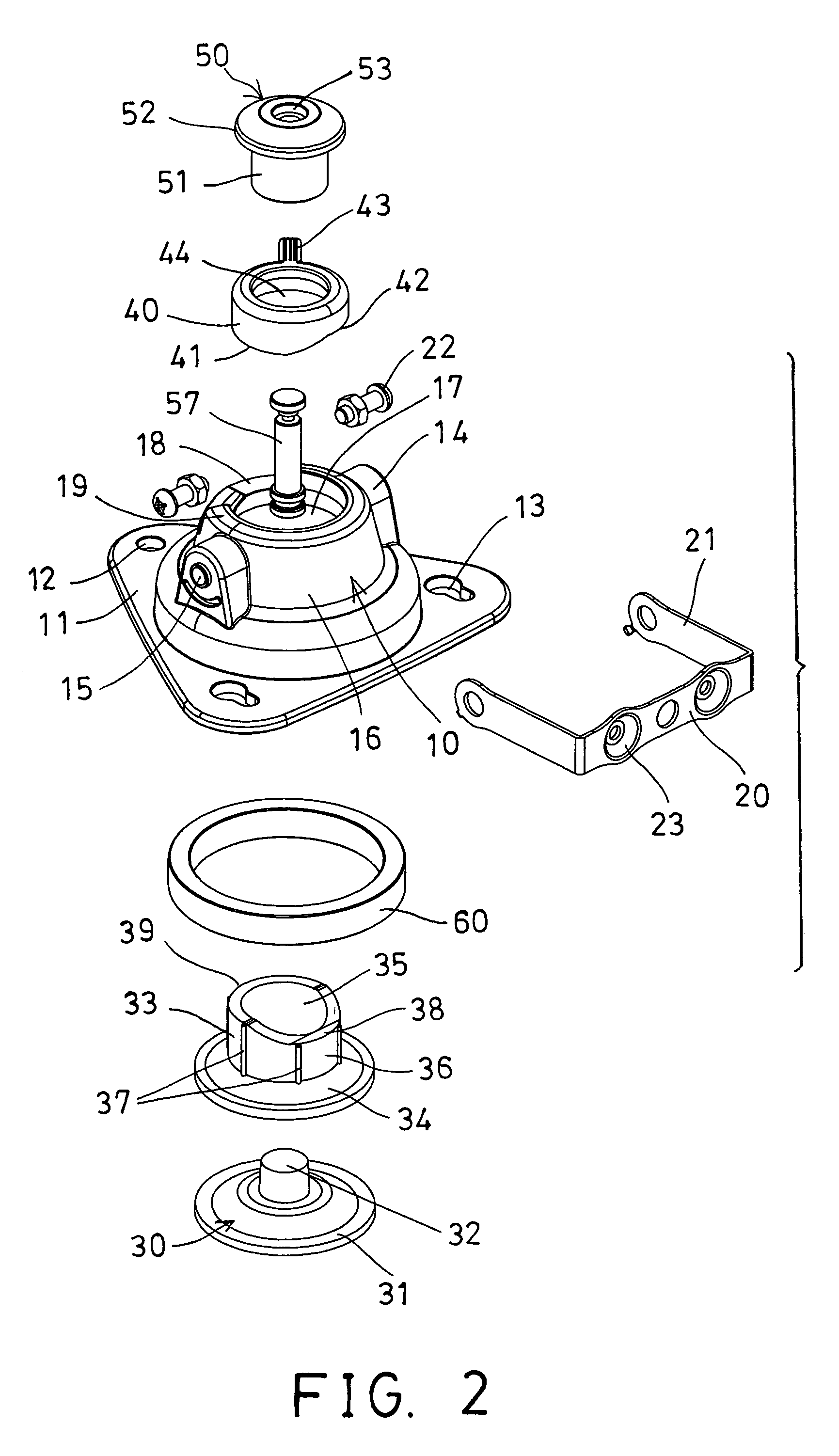
[0026]Referring to the drawings, and initially to FIGS. 1-4, an antenna mounting device in accordance with the present invention comprises a housing 10 including a base panel 11 for attaching or engaging onto various supporting facilities, such as wall members, window glasses, vehicle roofs, etc., and the base panel 11 includes one or more apertures 12 and / or one or more key holes 13 formed therein for securing or hanging onto the supporting facilities with such as fasteners, pegs, etc.

[0027]The housing 10 includes two opposite side brackets 14 each having a screw hole 15 formed therein, and includes an outer peripheral wall 16 having the brackets 14 oppositely formed or provided or extended from the outer peripheral wall 16, and includes a chamber 17 formed in the housing 10 and defined by the outer peripheral wall 16. The outer peripheral wall 16 includes a recessed channel 18 formed in the upper portion of the outer peripheral wall 16 and defined between two end shoulders or stop...


PUM


Abstract

An antenna mounting device includes a housing having a chamber formed by an outer peripheral wall, a suction cup and a base casing received in the housing, the base casing includes a lower seat and an upper seat disposed on top of an outer peripheral fence, a ring member is rotatably engaged onto the base casing and includes a bottom actuator and a recessed actuator for engaging with the lower seat and the upper seat of the base casing and for adjusting the ring member up and down relative to the base casing when the ring member is rotated relative to the base casing. A cap is coupled to the central coupling member of the suction cup with a stem for actuating the suction cup.

Description

BACKGROUND OF THE INVENTION[0001]1. Field of the Invention[0002]The present invention relates to an antenna mounting device, and more particularly to an antenna mounting device having a structure for easily and readily attaching an antenna member to various supporting facilities, such as wall members, window glasses, vehicle roofs, etc.[0003]2. Description of the Prior Art[0004]Typical antenna devices are required to be attached or mounted onto various supporting facilities, such as wall members, window glasses, vehicle roofs, etc. and comprise a radio frequency receiver for receiving signals, and a securing means having a felt covered attachment magnet for securing or attaching the antenna devices onto the supporting facilities.[0005]For example, U.S. Pat. No. 6,023,218 to Tremblay discloses one of the typical antenna devices also comprising a felt covered attachment magnet secured within a bottom of an antenna supporting housing for securing or attaching the antenna supporting hou...

Claims


Application Information

Patent Timeline
Patent Type & Authority Patents(United States)
IPC IPC(8): H01Q1/12H01Q1/32
CPCH01Q1/1221H01Q1/3275
Inventor CHAN, YAT TO
Owner JOYMAX ELECTRONICS CO LTD
Why Eureka
Try Eureka