Reservoir tank of a power steering system for a car

a technology of power steering system and reserve tank, which is applied in the direction of rotary clutches, fluid couplings, couplings, etc., can solve the problems of affecting the flow of power steering oil and forming bubbles inside the reservoir

Active Publication Date: 2007-08-28
HYUNDAI MOTOR CO LTD
View PDF15 Cites 21 Cited by
  • Summary
  • Abstract
  • Description
  • Claims
  • Application Information

AI Technical Summary

Problems solved by technology

A drawback of the above system is that bubbles often form inside the reservoir.
Upon the formation of bubbles, flow of the power steering oil is impeded.

Method used


Image

  • Reservoir tank of a power steering system for a car
  • Reservoir tank of a power steering system for a car
  • Reservoir tank of a power steering system for a car

Examples


Embodiment Construction

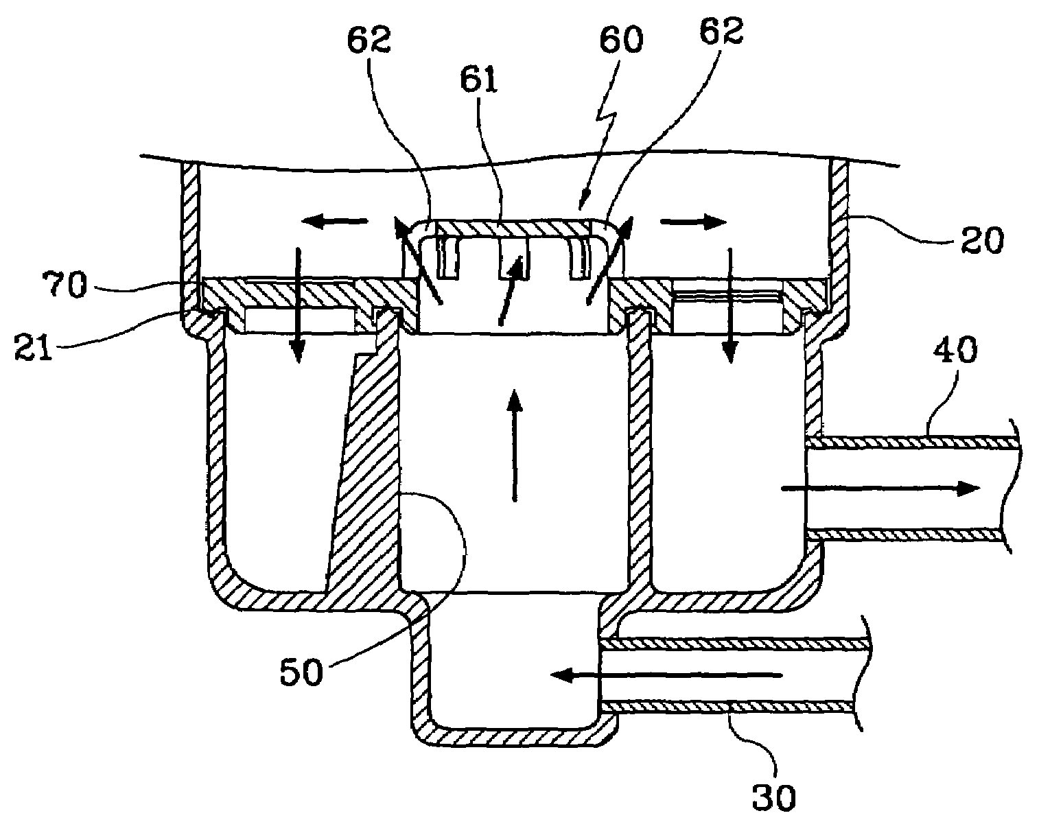
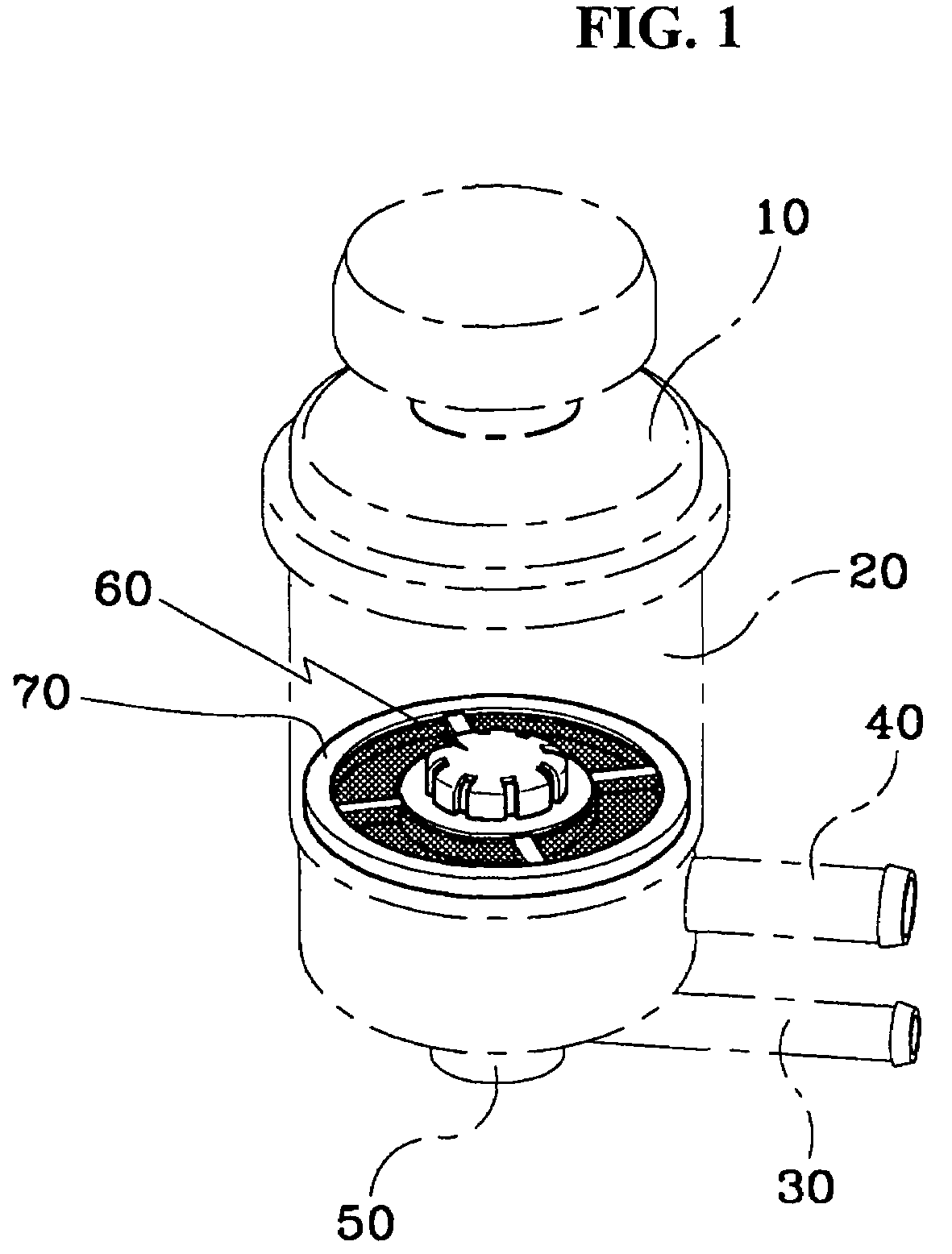
[0014]According to FIG. 1, a reservoir tank of a power steering system for a car includes an upper body 10 and a lower body 20. The upper body 20 is connected with an inlet port 30 to which oil from a power steering cylinder returns and an outlet port 40 that is located relatively above the inlet port 30 and sends out oil to the lower body 20 with an oil pump. A guide tube 50 guides power steering oil flowing in from an inlet port 30 to an upward direction. The guide tube 50 is formed and extends upward inside the lower body 20. The guide tube 50 is connected to the inlet port 30 and a swirl preventing means 60 is located at the tip of the guide tube 50. It can be desirable that the guide tube 50 is installed on the central axis of the lower body 20.

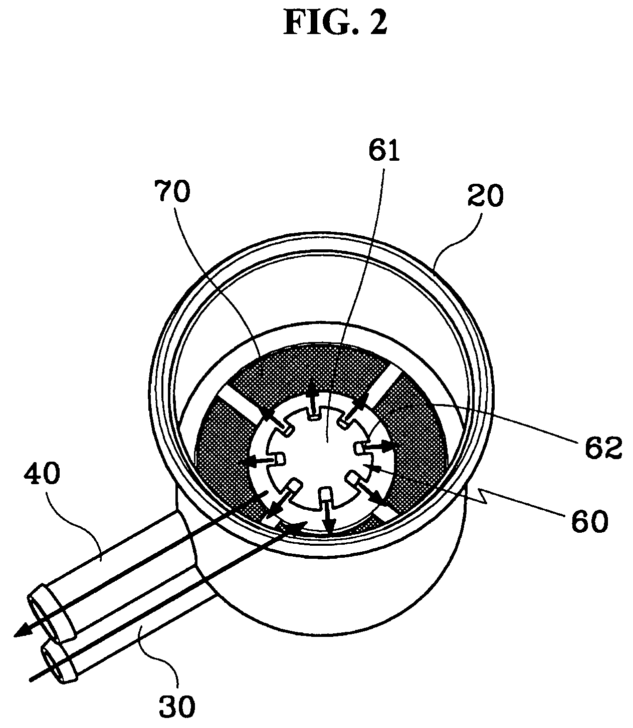
[0015]According to FIG. 3, a partition means 61 is positioned within the swirl preventing means 60 to distribute the oil flowing in from the guide tube 50. A plurality of oil discharge openings 62 are formed on one side of the bottom of ...


PUM


Abstract

A reservoir tank of power steering system for a car includes an inlet port delivering oil through a swirl prevention member. The oil is then allowed to flow so swirl does not form in the oil flow of a reservoir tank. Furthermore, bubble formation in the oil is minimized.

Description

CROSS REFERENCE TO RELATED APPLICATIONS[0001]This application claims priority of Korean Application No. 10-2003-0077542, filed Nov. 4, 2003, the disclosure of which is incorporated herein by reference.TECHNICAL FIELD OF THE INVENTION[0002]The present generally relates to a reservoir tank of a power steering system for car. More specifically, a direction of oil flow in the reservoir tank is provided to prevent excessive formation of air bubbles.BACKGROUND OF THE INVENTION[0003]Typically, an automobile steering system controls the steering angle of a car. The system is used to change direction of the car while the car is moving. The system is a mechanical system that requires a large manipulation force to move wheels of the car to facilitate the direction change. To assist a driver, it has become conventional that a power steering system is used to offset the large manipulative force required such that easy and quick steering manipulation can accomplished.[0004]Such a power steering s...

Claims


Application Information

Patent Timeline
Patent Type & Authority Patents(United States)
IPC IPC(8): B60T11/26B62D5/07F15B21/047B60T17/06B62D5/06
CPCB60T17/06B62D5/062F15B21/047Y10T137/86212Y10T137/8122Y10T137/86228B62D5/07
Inventor KIM, MIN JUNG
Owner HYUNDAI MOTOR CO LTD
Why Eureka
Try Eureka