
Automatic liquid collection and disposal assembly

a technology of automatic liquid collection and assembly, applied in the direction of positive displacement liquid engine, piston pump, liquid fuel engine, etc., can solve the problems of prone to failure of float switch design, little design change, and well-known deficiencies

Inactive Publication Date: 2007-09-04
LITTLE GIANT PUMP
View PDF38 Cites 110 Cited by
  • Summary
  • Abstract
  • Description
  • Claims
  • Application Information

AI Technical Summary

Problems solved by technology

These switch designs have changed little over the past several years and continue to incur well known deficiencies.
Float switch designs are prone to failure due to such factors as wear of mechanical parts; wedging debris entanglement that prevents effective operation; and operational disconnect or maladjustment.
With each of these one can expect failure of the pump to maintain a desired liquid level in a collection vessel.
It is known that such switches can vary in reliability depending on the elevation of the installation, and the breather tubes commonly used to sense atmospheric pressure are often subject to obstruction.
Submersible pumps used in liquid disposal systems are susceptible to failure when the pumping elements become clogged or otherwise frozen.
Wastewater reservoirs usually contain debris that is drawn into the pump, and poor pump performance and pump damage follows.

Method used


Image

  • Automatic liquid collection and disposal assembly
  • Automatic liquid collection and disposal assembly
  • Automatic liquid collection and disposal assembly

Examples


Embodiment Construction

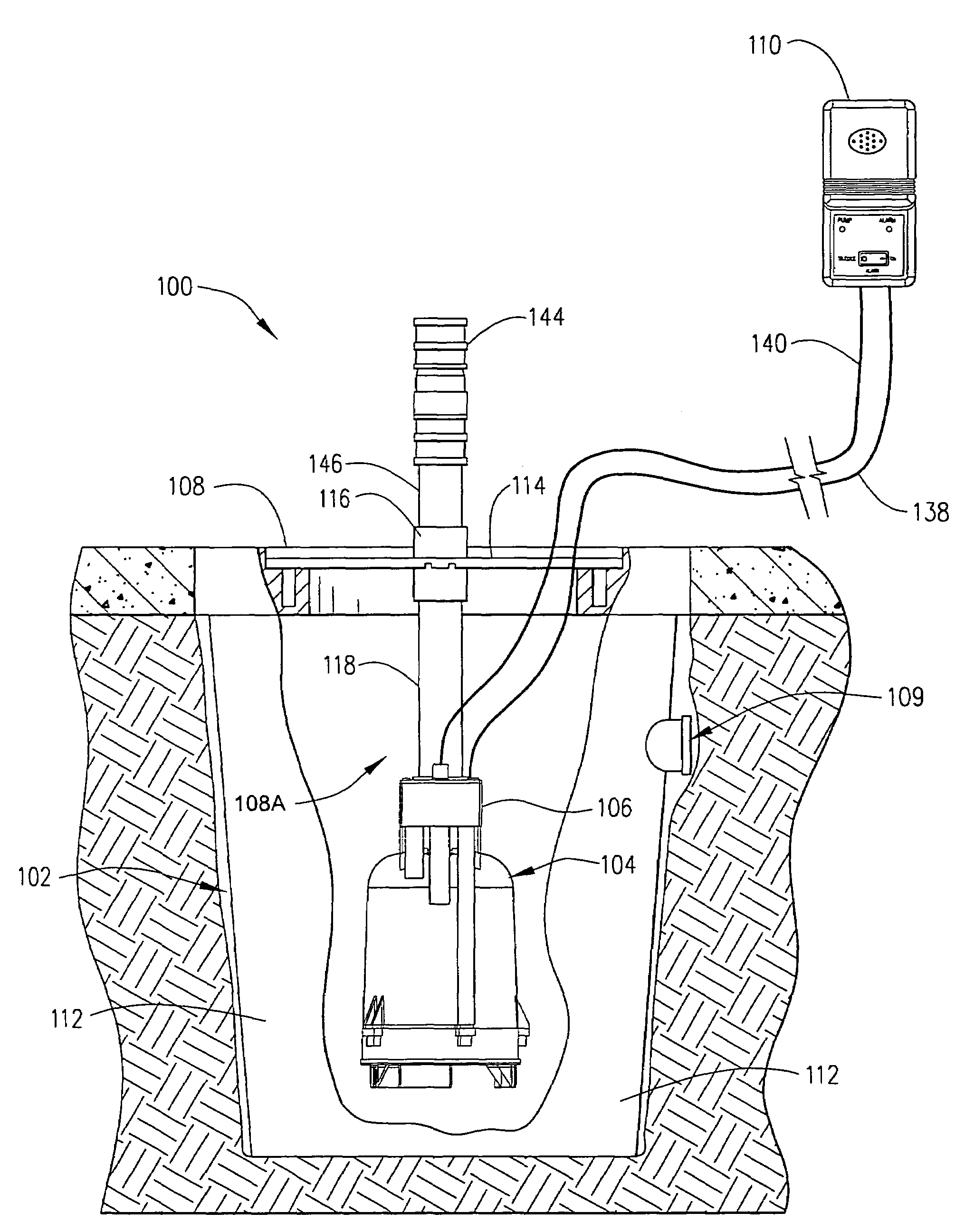
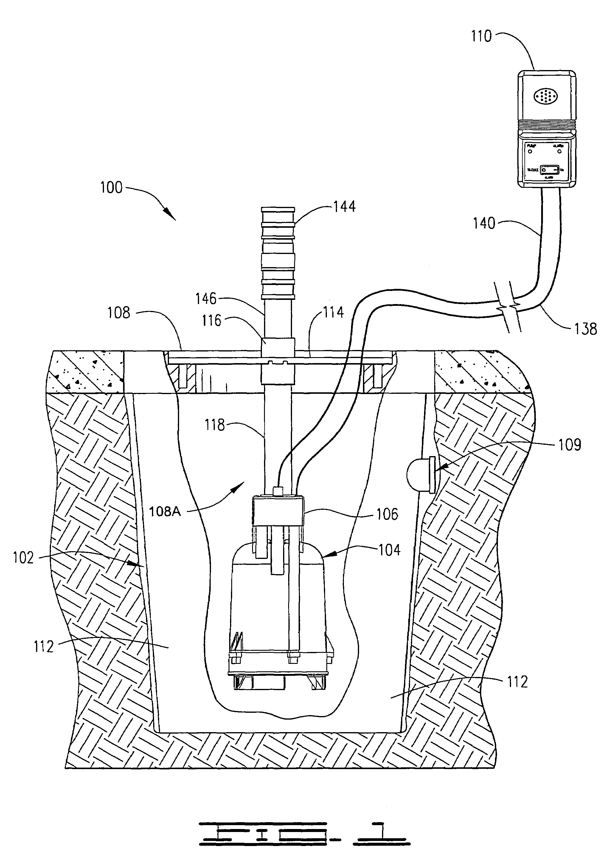
[0021]Referring to FIG. 1, shown therein is an automatic liquid collection and disposal assembly 100 that has been installed in an earthen pit 102. The automatic liquid collection and disposal assembly 100 includes a pump and motor assembly 104 with a liquid level detector 106 that are supported in a basin assembly 108 in the pit 102.

[0022]The basin 108 provides a collection cavity 108A for the accumulation of drainage liquids such as non-potable wastewater that enters a liquid entry port 109 that can be connected to a drainage conduit as required.

[0023]The automatic liquid collection and disposal assembly 100 has a control module 110 that is shown plugged into a nearby electrical outlet.

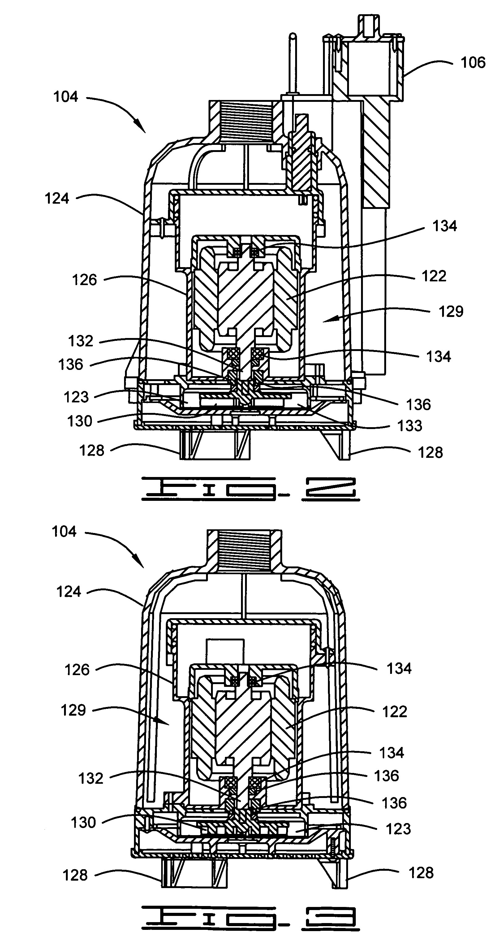
[0024]The construction and cooperative function of each of these components will be described with reference to FIG. 1 and with reference to the several other included figures in which the same number designations will be used to designate the components. Numerous details of construction will be omi...


PUM


Abstract

A liquid collection and disposal assembly for collecting and disposing of drainage liquid, the liquid collection and disposal assembly disposable in a pit and having a basin assembly with a collection cavity, a pump suspended in the collection cavity and a level detector to detect drainage liquid levels in the collection cavity. A controller responds to the level detector to activate the pump at predetermined levels of the drainage liquid to evacuate the drainage liquid. A transparent basin cover is supported on top of a basin member, and an effluent discharge pipe is connected to the basin cover and to a liquid outlet port of the pump, thereby supporting the pump a predetermined distance above the bottom of the collection cavity. The pump has a water jacket through which the discharging effluent passes to cool the motor.

Description

RELATED APPLICATIONS[0001]This application is a continuation of non-provisional application Ser. No. 10 / 383,502 filed Mar. 7, 2003 now abandoned, entitled Automatic Sump Pump Assembly, which claims domestic priority under 35 U.S.C. §119(e) to U.S. Provisional Application No. 60 / 362,426 filed Mar. 7, 2002, entitled Submersible Automatic Pump.FIELD OF THE INVENTION[0002]The present invention relates generally to pump assemblies, and more particularly but not by way of limitation, to an automatic liquid collection and disposal assembly.BACKGROUND OF THE INVENTION[0003]Liquid disposal systems are generally used for the evacuation of drainage liquids, usually non-potable wastewater, in a large number of applications. Examples of such applications are found in residence and business building sites that are subject to drainage liquid collection, such as where shallow underground water levels cause wall seepage or where ground water runoff accumulates. Whatever the source of liquid collecti...

Claims


Application Information

Patent Timeline
IPC IPC(8): F04B49/02
CPCF04D15/0218F04D29/588F04D13/086
Inventor HARNED, DICKTUSTEN, BILL
Owner LITTLE GIANT PUMP
Learn More