Supercharge Your Innovation With Domain-Expert AI Agents!

Seat belt tension sensor having an integral connector

a technology of seat belt and connector, which is applied in the direction of instruments, pedestrian/occupant safety arrangements, force/torque/work measurement apparatus, etc., can solve the problems of small children, people of smaller size and small children, and the chance of being injured by the impact of the inflating bag is higher

Inactive Publication Date: 2007-09-25
CTS CORP ELKHART
View PDF54 Cites 4 Cited by
  • Summary
  • Abstract
  • Description
  • Claims
  • Application Information

AI Technical Summary

Problems solved by technology

However, since their incorporation into automobiles, a problem has existed with people of smaller size and small children.
A smaller person may be injured by a bag inflating at this higher inflation force.
A smaller person is more likely to be sitting close to the dashboard and would therefore stand a higher chance of being injured by the impact of the inflating bag, as opposed to the passenger hitting the fully inflated bag to absorb the impact of the accident.
An average-sized person can also be injured by an airbag inflation if they are leaning forward, as for example, if they are adjusting the radio.
However, if the seat belt is unduly tightened, it can place an additional downward force on the passenger, creating an erroneous weight reading.

Method used


Image

  • Seat belt tension sensor having an integral connector
  • Seat belt tension sensor having an integral connector
  • Seat belt tension sensor having an integral connector

Examples


Embodiment Construction

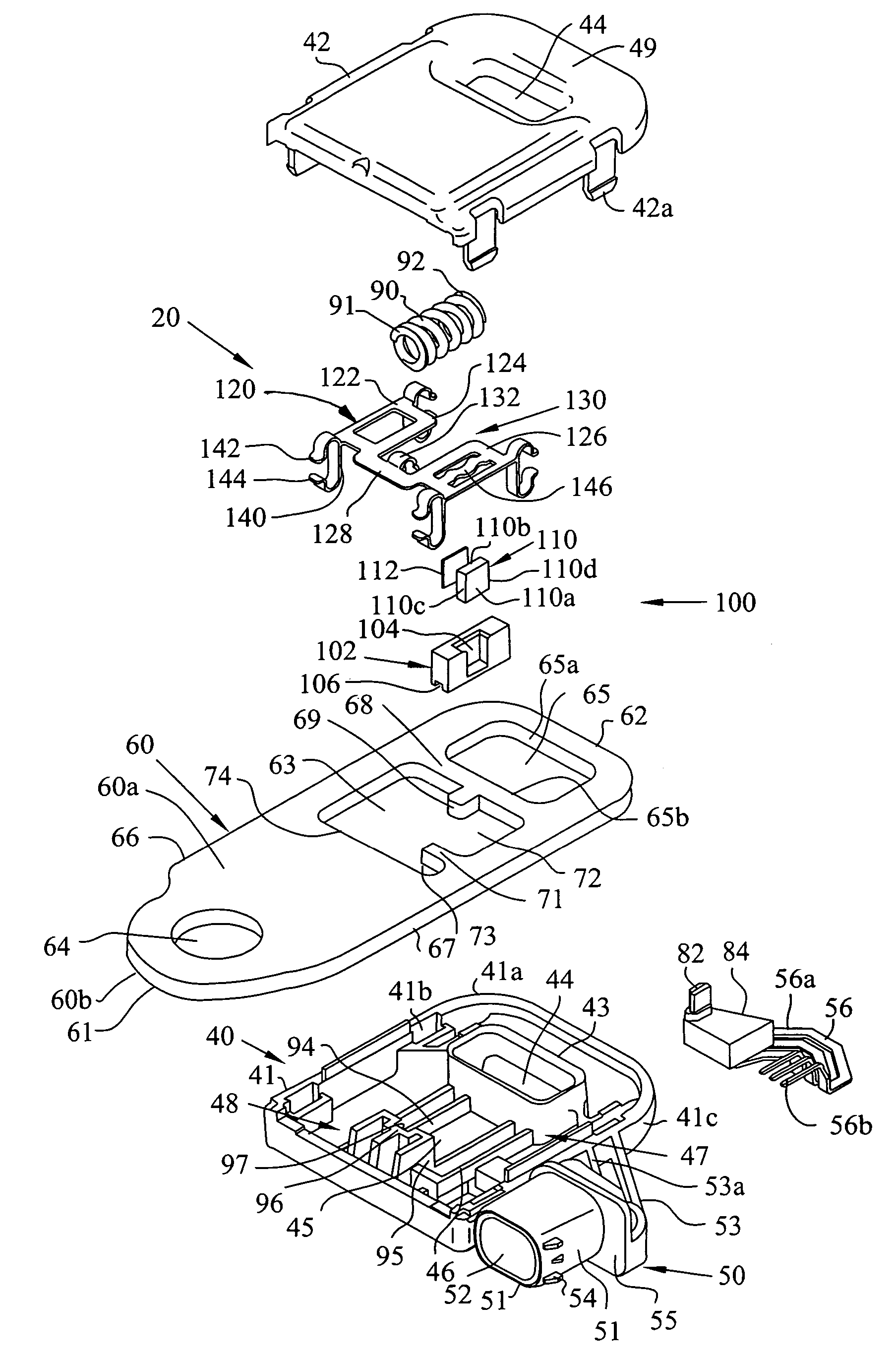
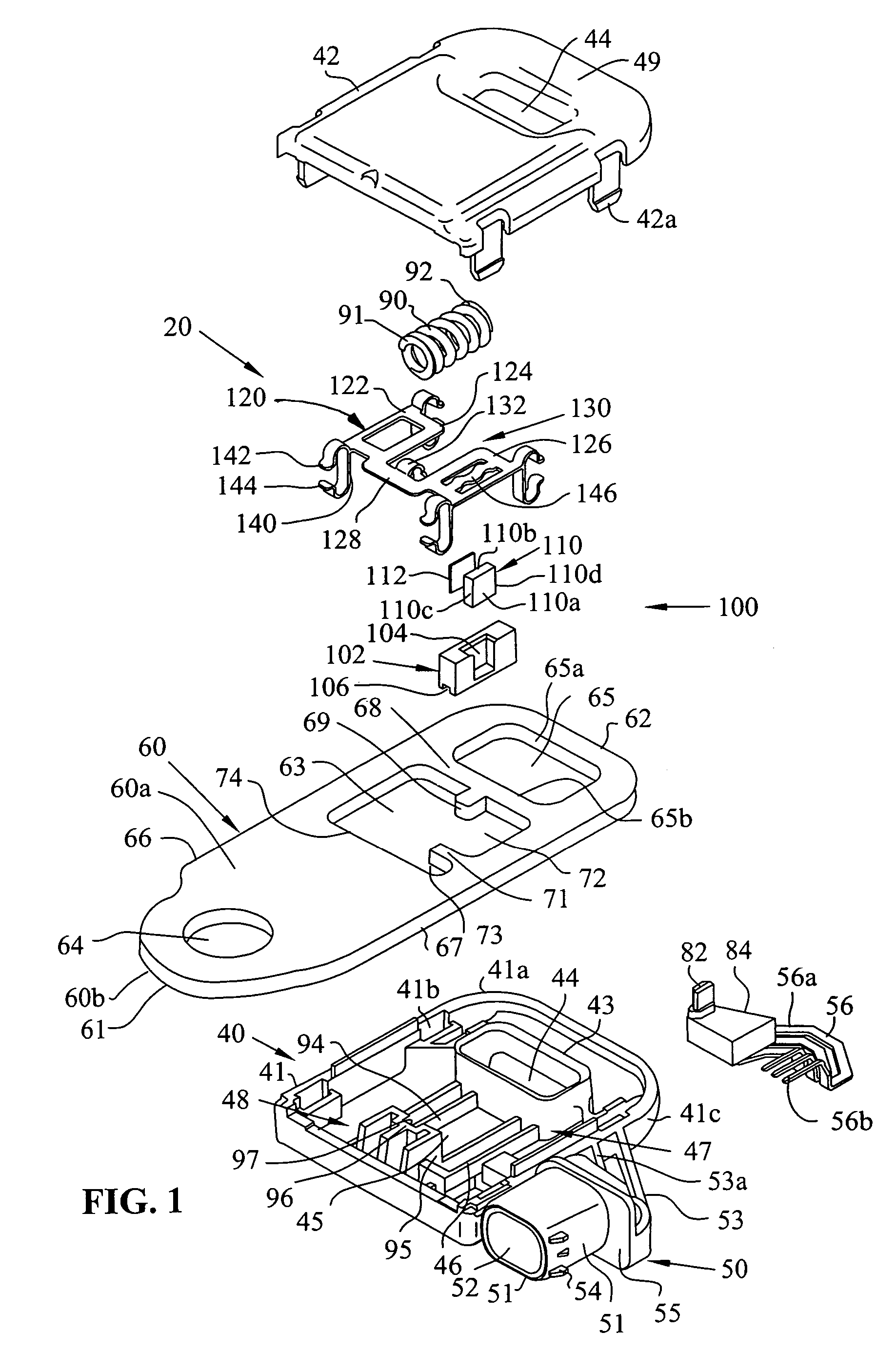
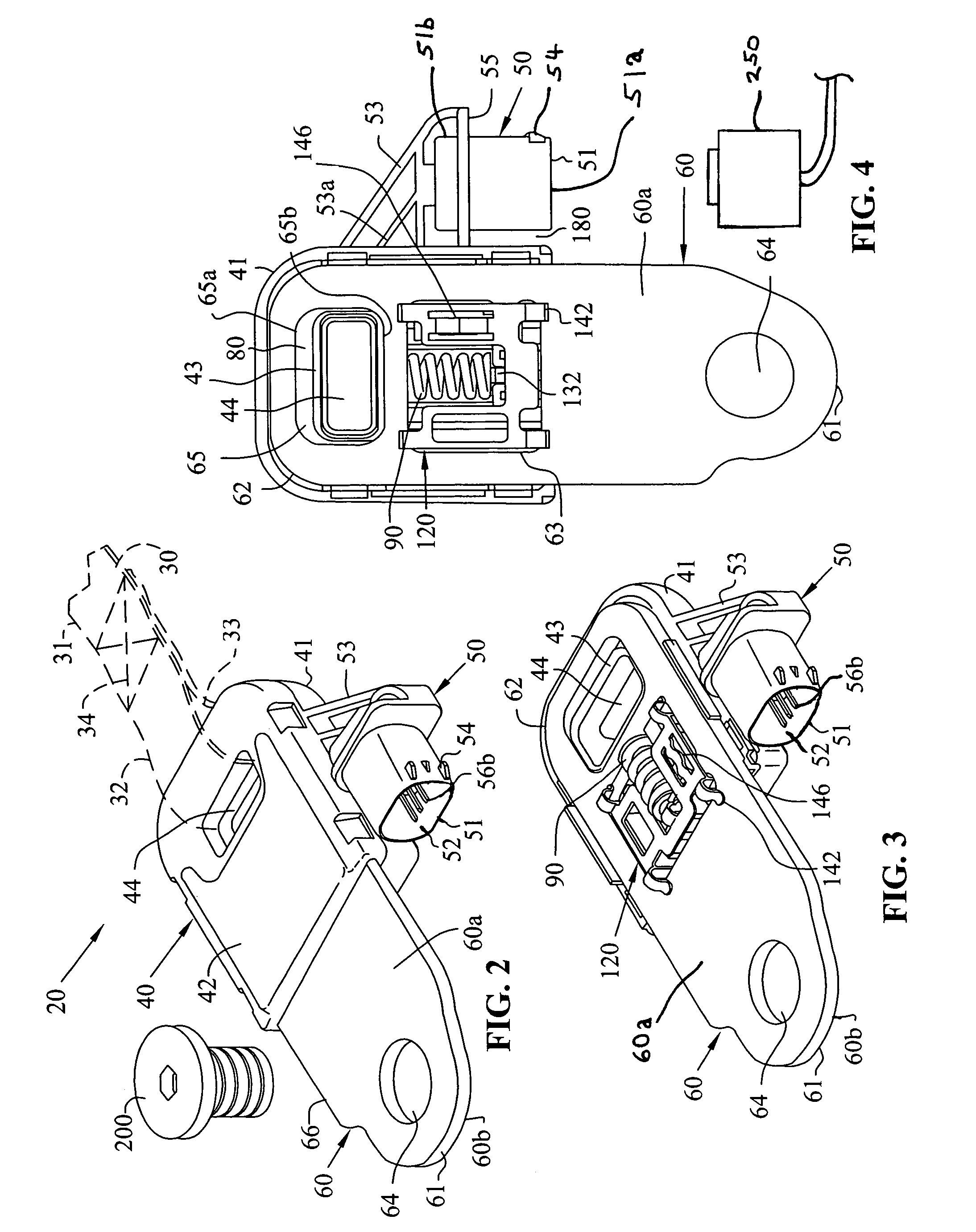
[0019]The present invention is a seat belt tension sensor. Referring to FIGS. 1-4, a seat belt tension sensor assembly 20 is shown. Assembly 20 has a housing 40 and anchor plate 60. Housing 40 is fastened between a seat belt webbing 30 and a structural part of the vehicle such as a floor (not shown). The belt webbing 30 has an end 31, an end 32, a belt loop 33 and stitching 34 that retains end 32.

[0020]Housing 40 has a bottom portion 41, top portion 42, flange 43, hole 44, spring channel 45, bearing rail 46 and sensor mounting area 47. A cavity 48 is located within housing 40. The bottom portion 41 and top portion 42 connect together to form housing 40 and are held together by snap fitting tabs 42a in to slots 42b. Alternatively, ultrasonic welding along lip 41A can connect portions 41 and 42 together. Housing portion 42 has a recess or narrow portion 49 on an end of the housing where the seat belt wraps around.

[0021]An integral connector 50 extends from housing bottom portion 41. C...


PUM


Abstract

A seat belt tension sensor for measuring the amount of tension in a vehicle seat belt. The seat belt tension sensor has a housing and an anchor plate that is mounted in the housing. The housing moves relative to the anchor plate. A magnet is affixed to the anchor plate. A sensor is mounted to the housing. The sensor generates an electrical signal in response to relative movement between the housing and the anchor plate. The electrical signal changes in proportion to the amount of tension on the seat belt. A spring is mounted between the housing and the anchor plate. The spring biases the housing from the anchor plate. An integral connector extends from the housing.

Description

CROSS-REFERENCE TO CO-PENDING AND RELATED APPLICATIONS[0001]This application is a continuation-in-part of U.S. patent application Ser. No. 10 / 388,816, filed Mar. 14, 2003, now U.S. Pat. No. 7,086,297 and titled, “Seat Belt Tension Sensor Having Shock Isolation”, which is a continuation-in-part of U.S. patent application Ser. No. 09 / 923,151, filed Aug. 6, 2001, now U.S. Pat. No. 6,578,432 and titled, “Seat Belt Tension Sensor”, which is a continuation-in-part of U.S. patent application Ser. No. 09 / 884,615, filed Jun. 19, 2001, now U.S. Pat. No. 6,647,811 and titled, “Seat Belt Tension Sensor”.[0002]This application is related to U.S. Pat. No. 6,729,194, issued May 4, 2004 and titled, “Hall Effect Seat Belt Tension Sensor”.BACKGROUND[0003]The foregoing pending applications and issued patents are herein incorporated by reference in their entirety.[0004]1. Field of the Invention[0005]This invention relates to an automobile sensor for detecting the magnitude of a tensile force in a seat ...

Claims


Application Information

Patent Timeline
Patent Type & Authority Patents(United States)
IPC IPC(8): B60R22/18B60R21/015
CPCB60R22/18G01L5/101G01L5/108B60R21/01516B60R21/01556G01L5/103B60R2021/01272B60R21/0155
Inventor KAIJALA, MURRAY
Owner CTS CORP ELKHART
Features
  • R&D
  • Intellectual Property
  • Life Sciences
  • Materials
  • Tech Scout
  • Unparalleled Data Quality
  • Higher Quality Content
  • 60% Fewer Hallucinations
Learn More