Microdevice having an annular lining for producing an electrospray emitter

a micro-device and emitter technology, applied in the direction of diaphragms, fluid speed measurement, particle separator tubes, etc., can solve the problems of inferior dimensional control, low output, and limited performance of electrospray emitters

Inactive Publication Date: 2007-10-16
AGILENT TECH INC
View PDF18 Cites 69 Cited by
  • Summary
  • Abstract
  • Description
  • Claims
  • Application Information

AI Technical Summary

Problems solved by technology

The performance of an electrospray emitter is limited in large part by its overall geometry, which in turn is determined by the technique used to fabricate the emitter.
Such methods suffer from a number of drawbacks such as low output and inferior dimensional control.
While semiconductor surface micromachining fabrication techniques have been proposed, such techniques are not suitable for producing an emitter that protrudes from a lateral surface of a substantially planar device.
In addition, such microfluidic technologies may operate at extreme low flow rates, e.g., in the nanoflow regime.
This approach is problematic because it tends to require a larger sample volume, lower ionization efficiency, and / or compromise band resolution emerging from the outlet port.
However, the likelihood of success in implementing this approach depends greatly on the quality of the attachment operation, and the interface formed between the emitter and the microdevice.
However, these approaches also suffer from a number of drawbacks.
For example, while silicon ESI emitters can be made with very small tip diameters, integration of such emitters to additional microdevice functionalities can be difficult and costly.
In addition, while Parylene processing costs tend to be significantly lower than silicon processing costs, dimensional and geometrical control over Parylene-based emitters is lacking compared to silicon-based emitters.
While laser ablation is an effective technique for removing material from polymeric microdevices to form ESI emitters, there is a limit to the degree to which the geometric dimensions of emitters may be controlled.
Generally, it is difficult to form ESI emitters having an extremely small-diameter tip by removing material from polymeric materials through the use of laser ablation alone.
When emitters having uncontrolled geometries are placed in operation, unstable Taylor cones may be formed, especially at low flow rates and at low solvent concentrations.

Method used


Image

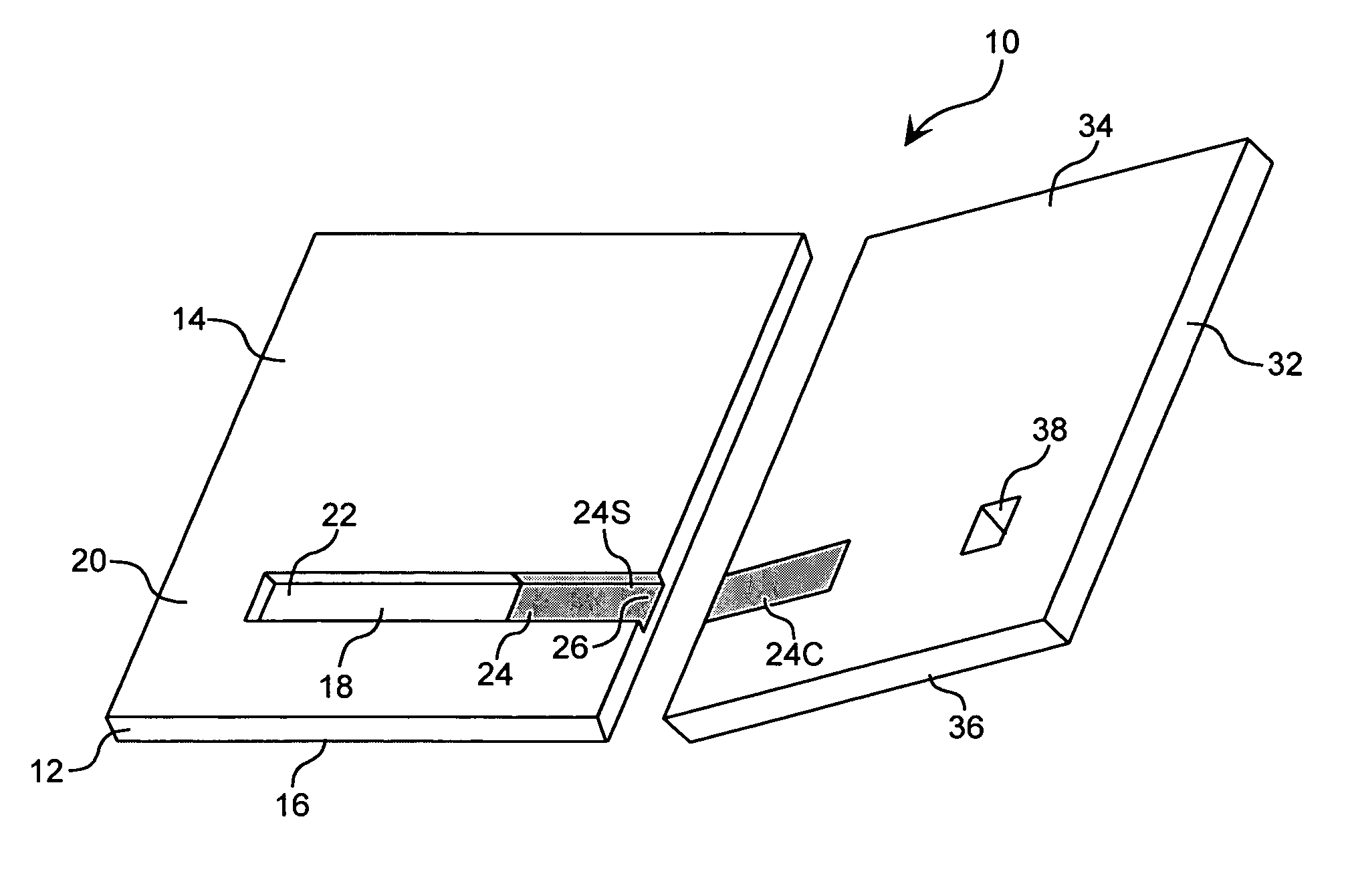
  • Microdevice having an annular lining for producing an electrospray emitter
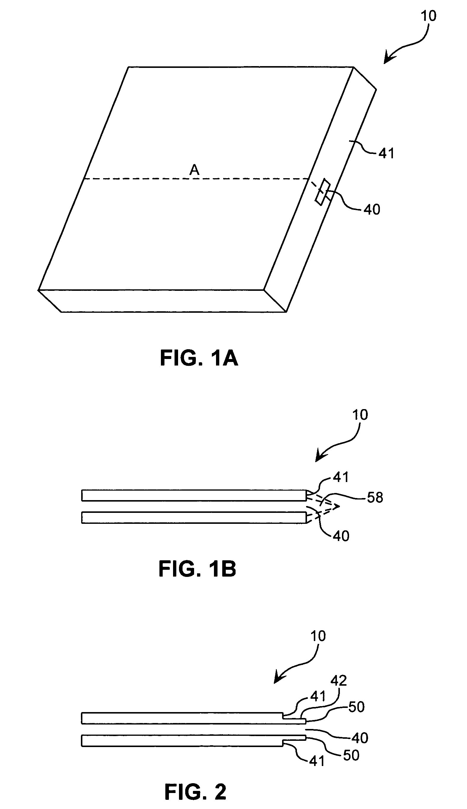
  • Microdevice having an annular lining for producing an electrospray emitter
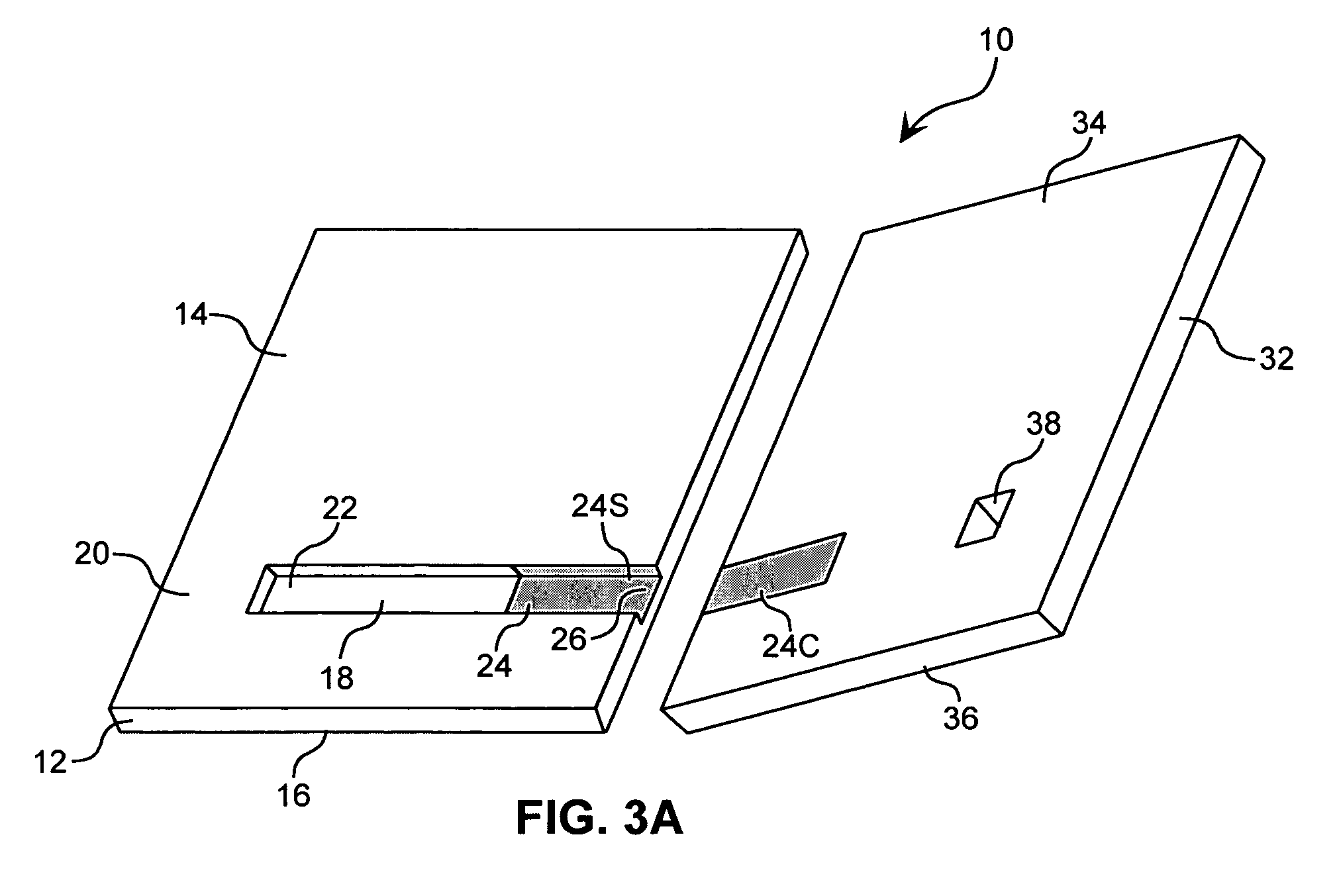
  • Microdevice having an annular lining for producing an electrospray emitter

Examples


Embodiment Construction

[0026]Before the invention is described in detail, it is to be understood that unless otherwise indicated this invention is not limited to particular materials, components or manufacturing processes, as such may vary.

[0027]It is also to be understood that the terminology used herein is for purposes of describing particular embodiments only, and is not intended to be limiting. It must be noted that, as used in the specification and the appended claims, the singular forms “a,”“an” and “the” include plural referents unless the context clearly dictates otherwise. Thus, for example, reference to “a material” includes a single material as well as a combination of materials, reference to “a conduit” includes one or more conduits, and the like.

[0028]In this specification and in the claims which follow, reference will be made to a number of terms which shall be defined to have the following meanings:

[0029]As used herein, the term “biofouling” refers to uncontrolled accumulation of biomateria...


PUM

PropertyMeasurementUnit
thicknessaaaaaaaaaa
thicknessaaaaaaaaaa
thicknessaaaaaaaaaa

Abstract

A microdevice is constructed from a substrate having a microchannel formed therein and a cover plate arranged over the substrate. The cover plate in combination with the microchannel at least partially defines a conduit within the microdevice. The conduit has a surface that extends from an upstream region toward a downstream region and terminates at an opening. The microdevice also includes an annular lining that conforms to the conduit surface at the downstream region and extends from the opening toward the upstream region in the conduit. An emitter may be produced in situ by depositing an emitter material on the annular lining. In addition, material may be removed from the cover plate and / or substrate about the opening. As a result, an exterior microdevice surface is formed and a downstream portion of the emitter is exposed that protrudes from the exterior surface.

Description

TECHNICAL FIELD[0001]The present invention generally relates to microdevices having electrospray emitters and to the production of such emitters. More specifically, the invention relates to the use of an annular lining that conforms to a downstream surface of a microdevice conduit to produce an electrospray emitter protruding from an exterior surface of the microdevice.BACKGROUND[0002]Electrospray ionization (ESI) technology allows ions to be produced from a liquid solution and introduced into an analytical device such as a mass spectrometer. Typically, an aerosol is produced in a spray chamber of the analytical device by passing a fluid sample through a capillary such that the capillary serves as an electrospray emitter and has a terminus subjected to an electric field within the chamber. The electric field is usually generated by placing a source of electrical potential, e.g., an electrode or sample introduction orifice, near the capillary terminus, wherein the source is held at a...

Claims


Application Information

Patent Timeline
Patent Type & Authority Patents(United States)
IPC IPC(8): H01J49/04F15C1/06B81B1/00G01N30/60G01N30/72H01J49/16
CPCB81B1/00H01J49/167G01N30/7266G01N30/6095Y10T137/2191Y10T137/2224
Inventor BRENNEN, REID A.
Owner AGILENT TECH INC
Why Eureka
Try Eureka