Burial service assembly and method

Active Publication Date: 2007-10-30
WILBERT FUNERAL SERVICES
View PDF17 Cites 0 Cited by
  • Summary
  • Abstract
  • Description
  • Claims
  • Application Information

AI Technical Summary

Benefits of technology

[0010]An assembly for displaying a vault cover and placing the cover onto a vault. The assembly includes a support structure that has a plurality of legs upon which first and second rails are secured. Each of the first and second rails has a first portion extending parallel to the ground and a second portion that extends downwardly from the first portion at an angle of less than 180 degrees.

Problems solved by technology

Though the system provides a means for placing a vault cover onto a vault base, problems with this system remain.
Furthermore, often the casket and cover are displayed simultaneously and the casket obscures the view of the vault cover adding to the viewing difficulties.
These viewing difficulties cause many problems such as individuals inadvertently causing cave ins by getting too close to the burial plot in order to see the vault cover.
Additionally by getting too close to the cover, individuals can accidentally bump or hit the cover causing it to move from its position on the tee rails, and in a worse case scenario cause the cover to fall.
Additionally, many times obstacles such as wreathes or flowers that are placed around the burial vault interfere with the ability of an individual to walk around the plot in order to see the vault cover.
Thus, this design causes for many instances where embarrassment may fall upon an attendee and makes viewing of the vault cover difficult.
However, this solution also causes its own set of problems.
Specifically, because of gravity and the large size and weight of the vault cover, there is difficulty in keeping the vault cover from rolling down the incline.
Thus, the incline must be very slight which is not optimal for viewing.
Furthermore, when the casket and the cover are displayed simultaneously the casket still continues to block the view of the vault cover.
Thus, problems as outlined above remain in that individuals still must walk up to the edge of the grave plot, or around the plot and casket to view the vault cover.

Method used


Image

  • Burial service assembly and method
  • Burial service assembly and method
  • Burial service assembly and method

Examples


Embodiment Construction

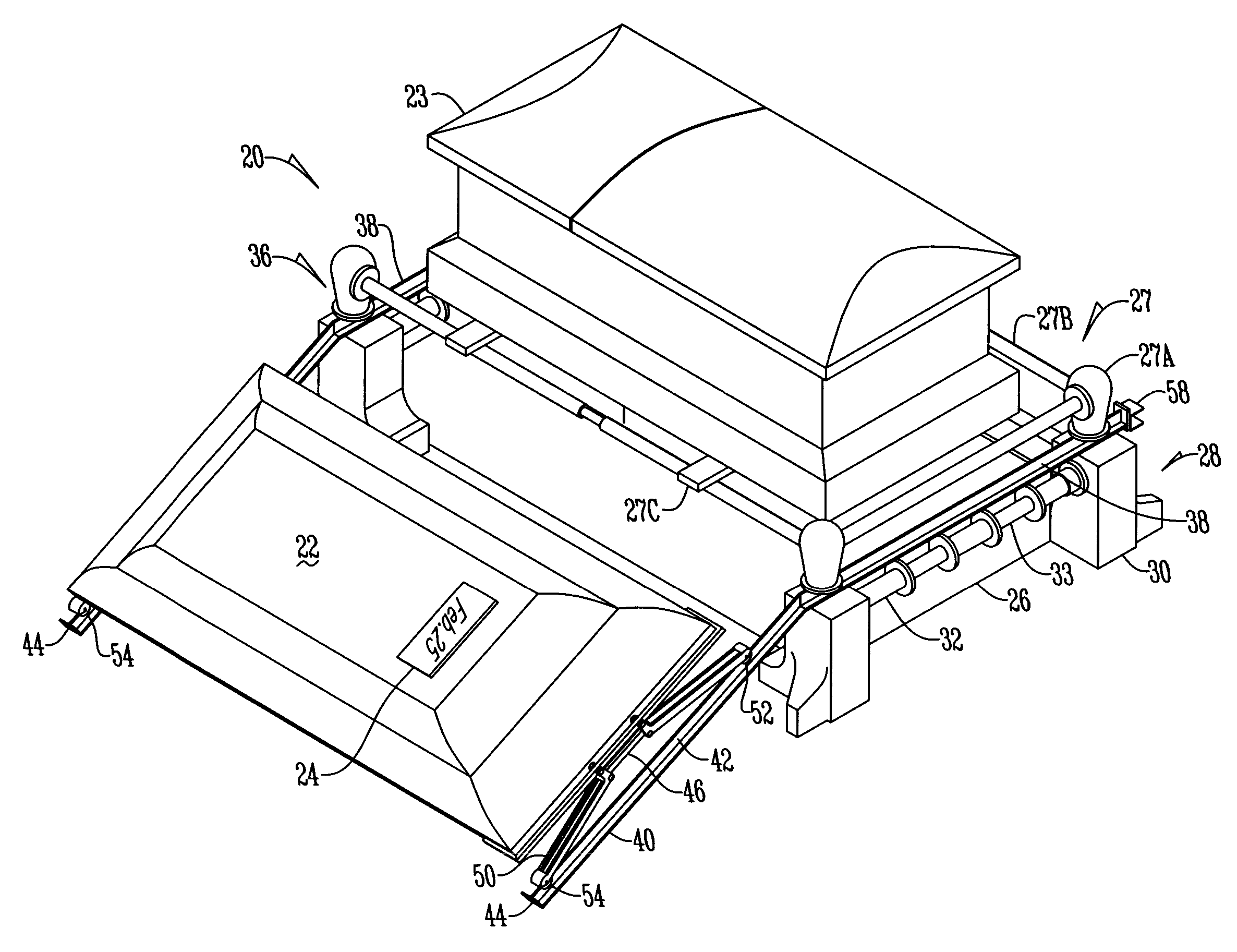
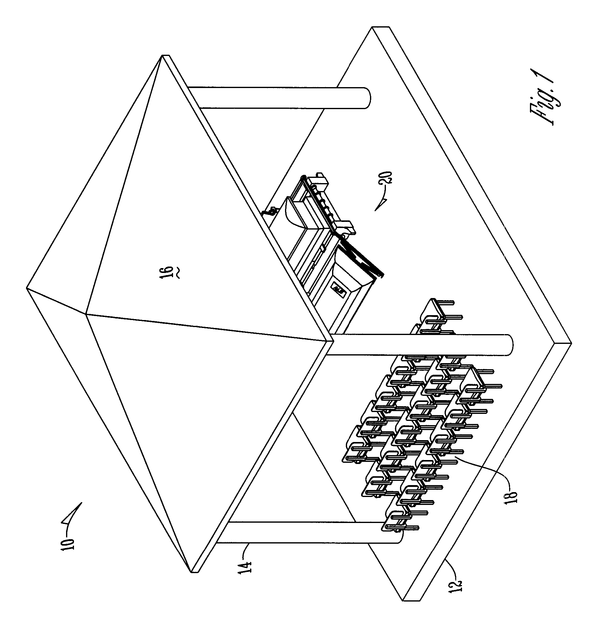
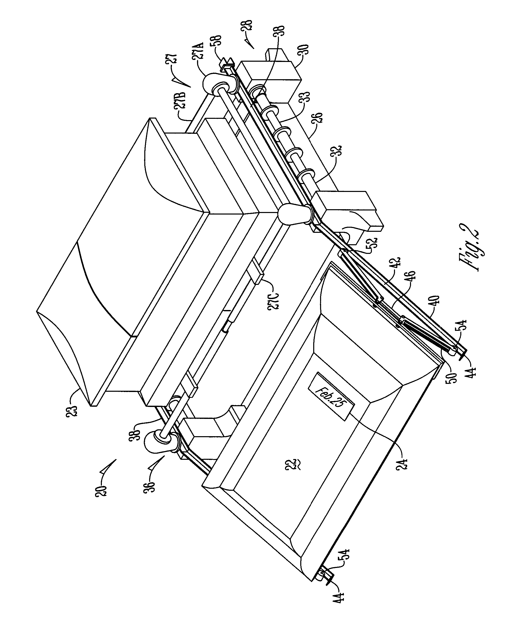
[0017]FIG. 1 shows a burial service site 10 having a rigid base structure 12. Extending from the rigid base structure 12 is a plurality of supporting members 14 that support a canopy 16. Within the burial service site 10 is a seating area 18 for individuals attending a funeral. Housed within the burial service site 10 is a burial vault display assembly 20 that is used in order to display a vault cover 22 and a casket 23 simultaneously. (See FIG. 2). The vault cover 22 has adoring features 24 such as for example emblems, special engravings, or dates thereon for viewing by attendees and is placed on a vault base 26. As shown in FIG. 2 a casket lowering device is removably placed on the burial vault display assembly for displaying the casket 23. The casket lowering device 27 is comprised of a plurality of decorative posts 27a connected with metal tubing 27b. A pair of casket holding rails 27c extend across the metal tubing 27b such that the casket 23 rests upon the casket holding rails...


PUM


Abstract

A burial vault assembly for displaying a vault cover and placing the cover onto a vault base. The assembly has a support structure with a first and second rail secured to the top of a support structure. Each rail has a first portion and a second portion that extends towards the seating area of the burial site and at a downward angle from the first portion. Each rail additionally at the end of its second portion has a stopping element. Thus, a burial cover is moveable along the first and second rails from a sealing position to a display position wherein the vault cover is stopped in place by the stopping element.

Description

BACKGROUND OF THE INVENTION[0001]This invention relates to burial vaults. More specifically, this invention relates to an assembly for displaying and placing a funeral vault cover onto a vault base.[0002]During a funeral service at a cemetery an assembly is set up that allows a vault cover to be displayed and lowered onto a vault base. Presently this is done using a support system that has tee rails attached thereto that have a cantilevered span that extends away from the attendees in the seating area of the funeral. A pair of cover carriages are then placed on the tee rails such that the tee rails form a track for the cover carriages. The cover carriages are thus secured to the vault cover to allow movement of the cover along the tee rails. Thus, the vault cover is moveable from a position over the top of the vault to a position away from the vault.[0003]Though the system provides a means for placing a vault cover onto a vault base, problems with this system remain. Specifically, m...

Claims


Application Information

Patent Timeline
IPC IPC(8): A61G19/00
CPCE04H13/001
Inventor PETERSON, MICHAEL L.MANRIQUE, TONYNORDER, PHILLIP
Owner WILBERT FUNERAL SERVICES
Why Eureka
Try Eureka