Display optical system and image projector

a technology of optical system and image, applied in the direction of projectors, color television details, instruments, etc., can solve the problems of distortion of images, difficult to provide a lens structure suitable for reflection, and difficult to make the projected images of each color completely coincide on the projection surface, etc., to achieve the effect of shortening the combined focal length of the projection lens

Inactive Publication Date: 2007-10-30
CANON KK
View PDF12 Cites 13 Cited by
  • Summary
  • Abstract
  • Description
  • Claims
  • Application Information

AI Technical Summary

Benefits of technology

[0013]The display optical system separates light from the light source into a first color component, a second color component having a shorter wavelength than the first color component, and a third color component having a longer length than the first color component, guides the first to third color components to first to third reflective light-modulating devices, respectively, combines the first to third color components from the first to third reflective light-modulating devices, respectively, and guides the combined color components to the projection lens. The optical curved-surfaces of the display optical system are disposed in light paths of the second and third color components so as to shorten the combined focal length of the projection lens and the second and third reflective light-modulating devices in comparison to the focal length of the projection lens for the first color component.
[0014]The display optical system separates light from the light source into a first color component, a second color component having a shorter wavelength than the first color component, and a third color component having a longer wavelength than the first color component, guides the first to third color components to the first to third reflective light-modulating devices, respectively, combines the first to third color components from first to third reflective light-modulating devices, respectively, and guides the combined color components to the projection lens. The optical curved-surfaces of the display optical system is disposed in a light path of the first color component so as to lengthen the combined focal length of the projection lens and the first reflective light-modulating device in comparison to the focal lengths of the projection lens for the second and third color components.

Problems solved by technology

When colors are combined using a known color-combining prism and a projection lens, it is difficult to make the projected images of each color completely coincide on a projection surface, such as a screen, because of the lateral chromatic aberration of the projection lens.
Therefore, it is difficult to provide a lens structure suitable for a reflective liquid crystal projector having a wide-angle lens since lateral chromatic aberration of the reflective liquid crystal projector tends to become large.
However, since the color-combining system of the display optical system disclosed in Japanese Patent Laid-Open No. 8-201756 includes two dichroic mirrors and a reflective mirror, in addition to the lateral chromatic aberration caused by the projection lens, distortion of the image occurs because the color channels of the light transmitted through the dichroic mirrors are distorted due to the distortion of the surfaces of the dichroic mirrors.
As a result, the size of the projected image for each color channel does not match the calculated size, and, thus, the magnification for each color channel is not corrected effectively.
Therefore, in addition to the lateral chromatic aberration of the projection lens, deformation of the projected image occurs due to the bending of the dichroic mirror caused by angular error of the prisms.
Consequently, it is difficult to completely match the projected images for the three colors: red, green, and blue.
However, there is no disclosure made for correcting the lateral chromatic aberration for a reflective liquid crystal projector having a long back-focus.

Method used


Image

  • Display optical system and image projector
  • Display optical system and image projector
  • Display optical system and image projector

Examples


second embodiment

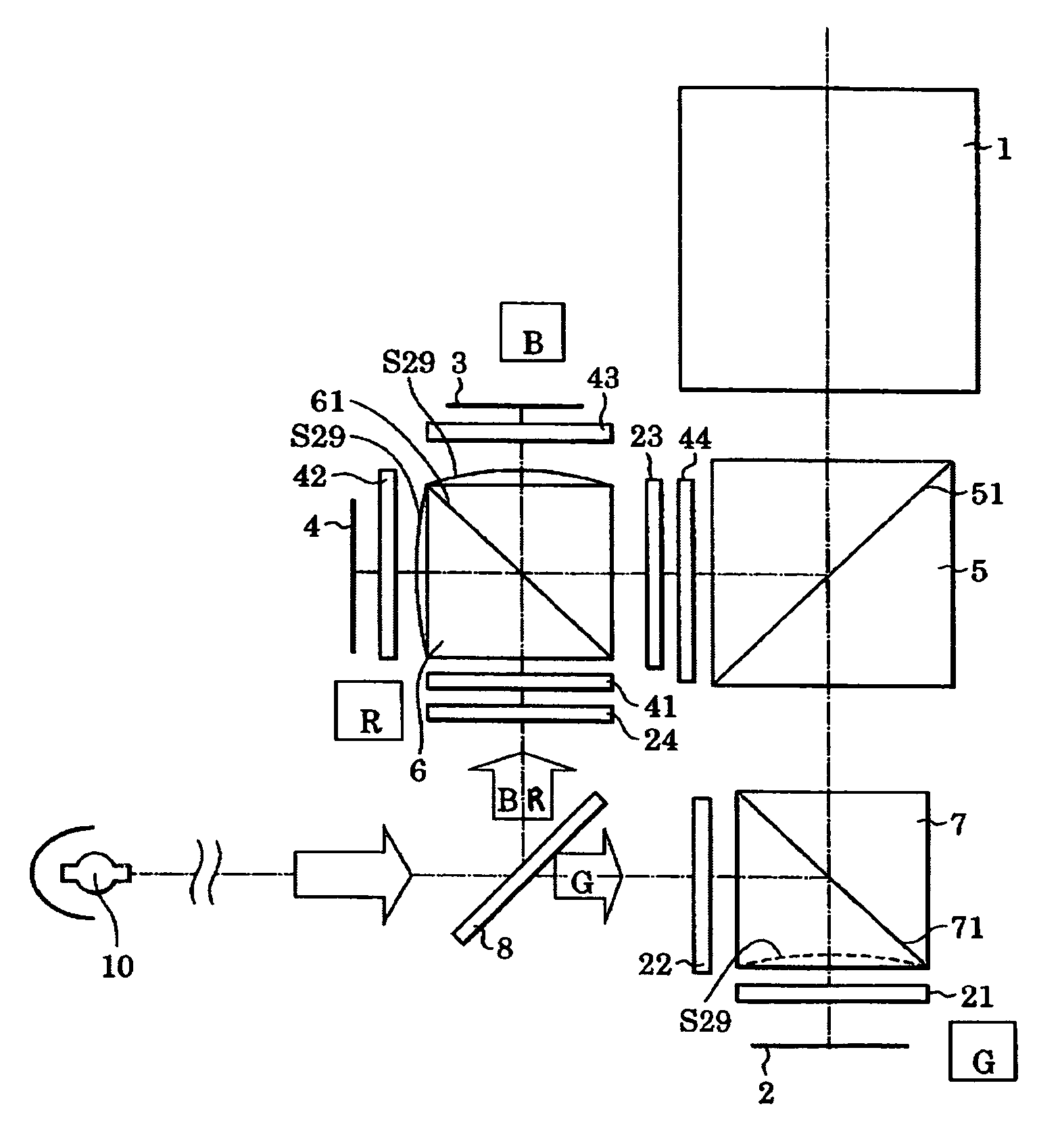
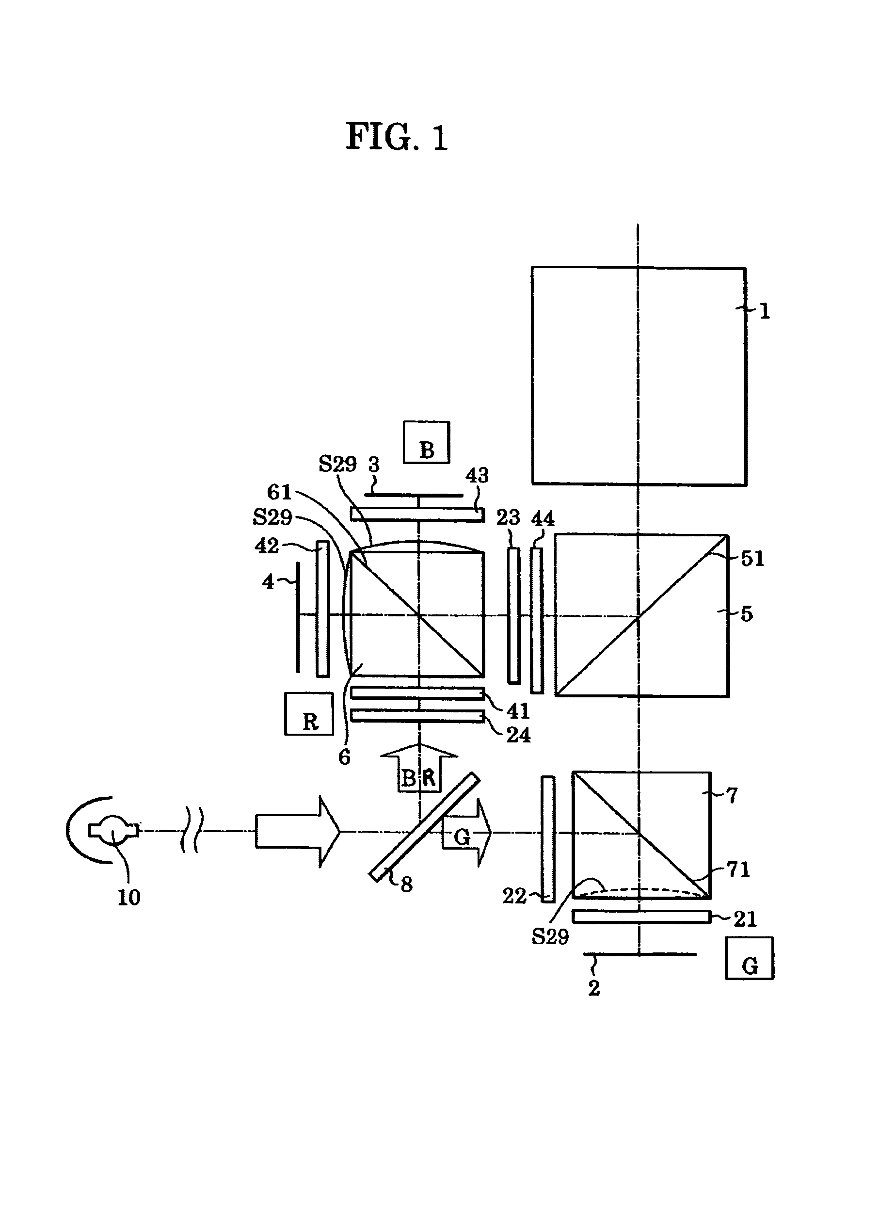
[0068]To relatively extend the focal distance of the green light component (that is, in order to make the size of the green projection image closer to the size of a red projection image or a blue projection image), the optical surface (for example, the optical curved-surface S29 of the first polarization beam splitter, as illustrated in FIG. 6) provided in the light path of the green light component may have diverging power. This structure is the structure in which the optical curved-surface is arranged in a green light path. In other words, it is the structure in which the prism surface facing the optical modulating device for green is the optical curved surface. This is referred to as the second embodiment and shown in FIG. 6.

[0069]FIG. 1 shows the configuration in which the first and second embodiments are combined. The separate optical curved surface is arranged in each of the red light path, blue light path, and green light path. The curvature of these optical curved surfaces m...

first embodiment

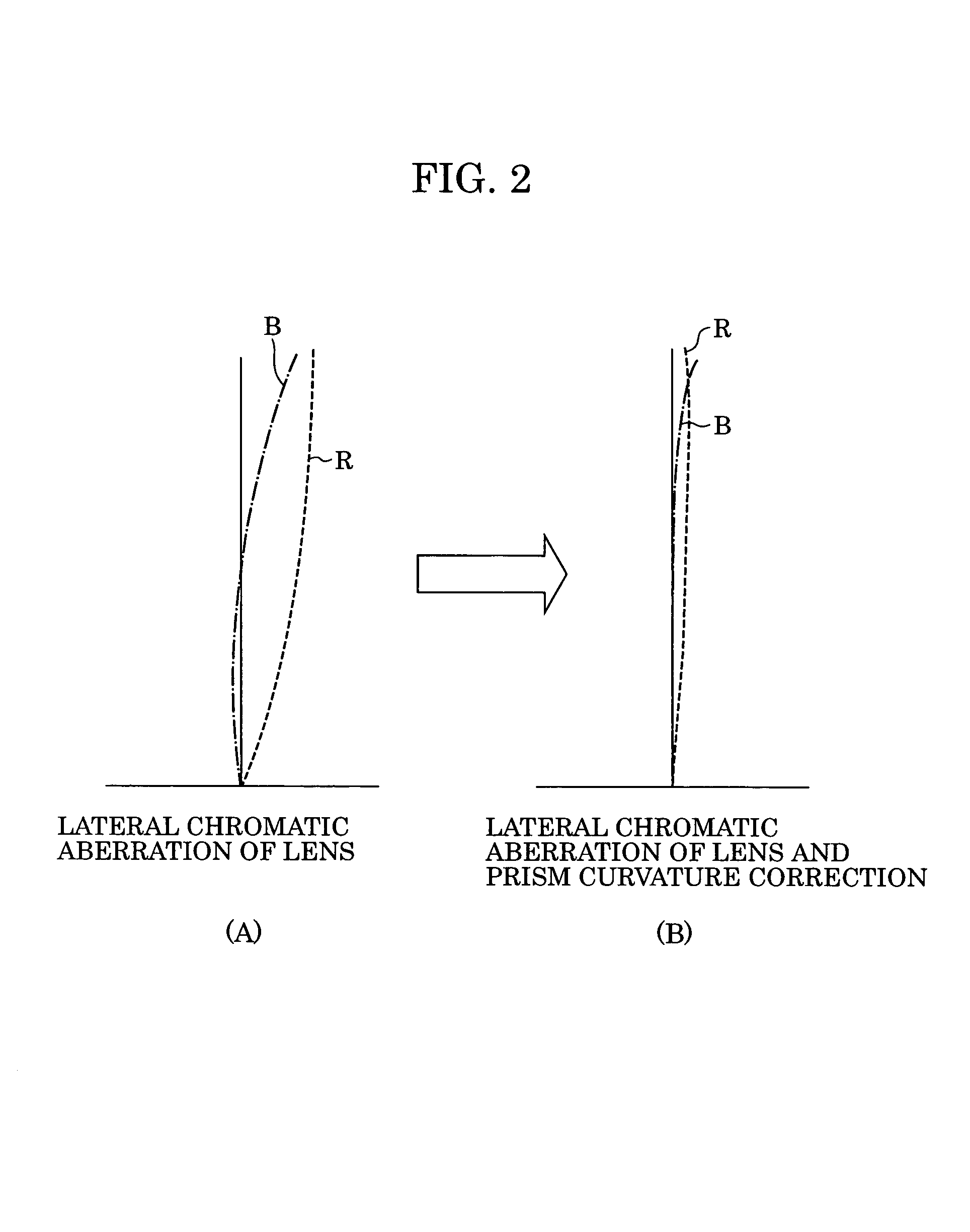
[0078]In FIG. 4B illustrating the present invention, an optical curved-surface is provided at a position closest to the light-modulating device in a light path common for both blue and red components. In this case, the lateral chromatic aberration of the blue component is significantly reduced compared to that in FIG. 4A, and the lateral chromatic aberration at the peripheral area of the image is reduced to 5 μm or less. The curvature r29 (the radius of curvature of optical curved-surface S29 of the light-modulating device in the second polarization beam splitter 6 illustrated in FIG. 3 and the optical curved-surface S29 illustrated as a convex surface with a solid line in FIG. 1) of an optical curved-surface provided in a light path of the blue and red components is set as follows:

r29=−20,000 mm

[0079]FIG. 4C illustrates the lateral chromatic aberration of a display optical system according to the second embodiment of the present invention, wherein the focal distance of the green co...


PUM

PropertyMeasurementUnit
wavelengthaaaaaaaaaa

Abstract

A display optical system and an image projector incorporating the same. The display optical system includes a light source operable to emit light; a plurality of reflective light-modulating devices; a plurality of optical elements; a projection optical system including at least one refractive lens; and an optical curved-surface having a finite radius of curvature and interposed between the projection optical system and at least one of the plurality of reflective light-modulating devices, wherein the optical elements are arranged to guide light from the light source to the reflective light-modulating devices and to guide outgoing light from the reflective light-modulating devices to the projection optical system, and wherein the at least one refractive lens of the projection optical system projects incoming light to a predetermined plane.

Description

BACKGROUND OF THE INVENTION[0001]1. Field of the Invention[0002]The present invention relates to a display optical system for projecting light from a reflective light-modulation device and to an image projector including the display optical system.[0003]2. Description of the Related Art[0004]When colors are combined using a known color-combining prism and a projection lens, it is difficult to make the projected images of each color completely coincide on a projection surface, such as a screen, because of the lateral chromatic aberration of the projection lens. In general, a reflective liquid crystal projector has a long back-focus compared to a transmissive liquid crystal projector. Therefore, it is difficult to provide a lens structure suitable for a reflective liquid crystal projector having a wide-angle lens since lateral chromatic aberration of the reflective liquid crystal projector tends to become large.[0005]Taking these problems into consideration, a display optical system c...

Claims


Application Information

Patent Timeline
Patent Type & Authority Patents(United States)
IPC IPC(8): G03B21/00G03B21/20G03B21/26G02B5/04G02B13/16G02B13/18G02B27/00G02B27/14G02F1/13G02F1/13357G03B21/14
CPCG02B27/0025G02B27/1026H04N9/317G03B21/14H04N9/3105G02B27/145G03B21/2066
Inventor NAKAYAMA, HIROKI
Owner CANON KK
Why Eureka
Try Eureka