Laser processing method and laser processing apparatus

a laser processing and laser processing technology, applied in the field of laser processing methods and an apparatus, can solve the problems of new aberration, difficulty in adjusting the aperture, so as to reduce the accuracy required of the distance between the lens and the lens. the effect of reducing the accuracy

Inactive Publication Date: 2010-10-05
SUMITOMO ELECTRIC IND LTD
View PDF28 Cites 7 Cited by
  • Summary
  • Abstract
  • Description
  • Claims
  • Application Information

AI Technical Summary

Benefits of technology

[0008]It is important to raise horizontal resolution in an xy-plane, which is orthogonal to the beam line (z-axis) in the laser processing which converges a laser beam at a narrow region. Sometimes laser beams are used for cutting, annealing or welding a part having a long depth (z-direction) of an object (a work piece). The depth (z-) direction processing requires a deep (long) focal depth. A shallow focal depth of a beam allows a small (z-direction) distance error to induce large dispersion of the beam power and invite shortage of power density at an object (a work piece) spot. A deep (long) local depth is important in the laser processing as well as a fine horizontal resolution. This invention aims to prolong the focal length.
[0133]The present invention, which lengthens the focal depth, succeeds in lowering the accuracy required of the distance between the lens and the object (a work piece). The present invention enables a pulse laser to bore deep holes with a constant diameter in the depth direction.

Problems solved by technology

However various kinds of aberration accompany refractive-type lenses.
In the case of continual laser beam processing using a refractive-type lens, the aberration of refractive lenses is a problem.
Pulse laser, in particular, ultrashort pulse laser processing causes new aberration owing to the narrowness of a pulse.
A shallow focal depth of a beam allows a small (z-direction) distance error to induce large dispersion of the beam power and invite shortage of power density at an object (a work piece) spot.
A shallow focal depth is undesirable, because light power does not penetrate into inner parts of a photoresist.

Method used


Image

  • Laser processing method and laser processing apparatus
  • Laser processing method and laser processing apparatus
  • Laser processing method and laser processing apparatus

Examples


embodiment 1

[0143]Laser FWHM Pulse width: Δt=120 fs (1.2×10⁻¹³ s)

[0144]Incident beam FWHM diameter: Δi=4.7 mm (w0=4.0 mm)

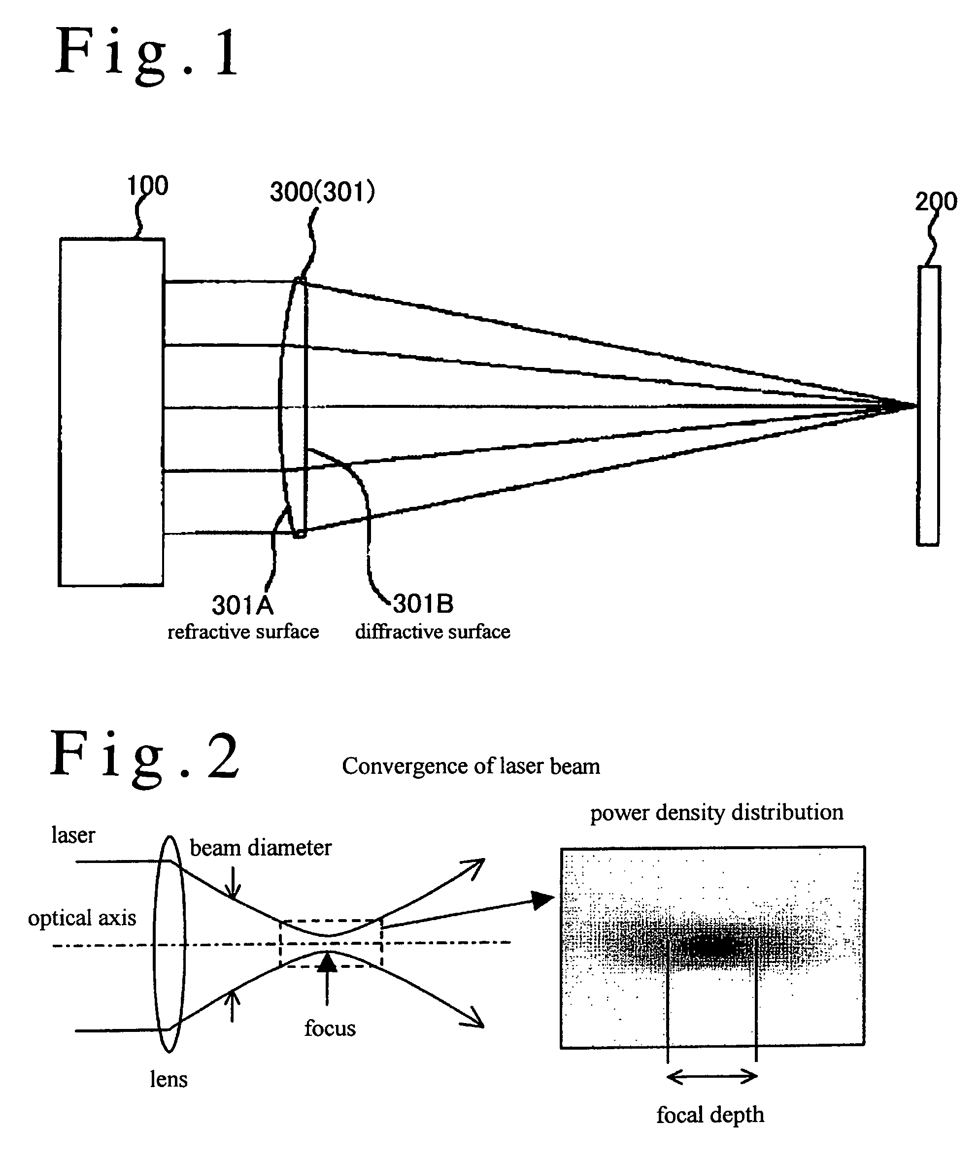
[0145]Lens Refractive Lens and Diffractive Lens

[0146]Focal Length: f0=100 mm

[0147]Z-parameter: 2f0cΔt / Δi2=0.32

[0148]The Z-parameter of 0.32 is between 0.25 and 1 (0.25<0.32<1), which satisfies the aforementioned requirement between 0.25≦Zp≦1.

[0149]The convergence properties of a refraction lens and a diffraction lens have been calculated on the abovecited conditions. FIG. 5 shows the results of calculations of power densities converged by the refraction lens and the diffraction lens. Left column figures of FIG. 5 demonstrate time-dependent spatial distributions of power density by the refractive lens. Right column figures of FIG. 5 show time-dependent spatial distributions of power density converged by the diffractive lens. The abscissa denotes distances. Individual figures have a length of 900 μm in the horizontal direction and a width in the vertical direction. Definition o...


PUM

PropertyMeasurementUnit
heightaaaaaaaaaa
wavelengthaaaaaaaaaa
focal lengthaaaaaaaaaa

Abstract

Ultrashort pulse laser processing bores, welds or cuts objects (work pieces) by converging ultrashort laser pulses by a lens on the objects (work pieces) positioned at the focus and heating small spots or narrow lines on the objects (work pieces). Shortage of a focal depth of the lens prevents the ultrashort pulse laser processing from positioning the object (a work piece) and forming a deep, constant-diameter cylindrical hole. Z-parameter is defined to be Z=2fcΔt / Δi2, where Δt is a FWHM pulse width of the ultrashort pulse laser, Δi is a FWHM beam diameter of the ultrashort pulse, f is a focal length of the lens and c is the light velocity in vacuum. Selection of an optical system including a diffraction-type lens which gives the Z-parameter less than 1 (Z<1) prolongs the focal depth. Expansion of the focal depth facilitates the positioning of objects (work pieces) and enables the ultrashort pulse laser apparatus to bore a deep, constant-diameter cylindrical hole.

Description

BACKGROUND OF THE INVENTION[0001]1. Field of the Invention[0002]This invention relates to a laser processing method and an apparatus of hole-boring, cutting or welding by irradiating objects (work pieces) with high power ultrashort pulse laser beams. Ultrashort pulse laser processing, which converges an ultrashort laser pulse by a lens and irradiates an object (a work piece) with the converged pulse, has an advantage of neither heating nor degenerating surrounding parts since heated regions are narrowly localized and ultrashort duration time gives no time of heat diffusion to the surrounding parts. The ultrashort pulse laser processing is a momentary, adiabatic processing. The ultrashort laser pulse processing is suitable for the processing of resins, glasses, quartz, sapphire, semiconductors, and so on.[0003]This application claims the priority of Japanese Patent Application No. 2004-336944 filed on Nov. 22, 2004, which is incorporated herein by reference.[0004]2. Description of Re...

Claims


Application Information

Patent Timeline
Patent Type & Authority Patents(United States)
IPC IPC(8): B23K26/38B23K26/40B29C65/16G02B3/08G02B5/18G02B13/00H01S3/00
CPCB23K26/0635B23K26/20B23K26/38B23K26/381B23K26/4065B23K26/4075B23K26/4025B23K26/407B23K26/408B23K2201/40B29C65/16B29C65/1603B29C65/1616B23K26/382B23K26/0624B23K26/40B23K26/21B23K2101/40B23K2103/42B23K2103/50B23K2103/52B23K26/06
Inventor SHIOZAKI, MANABUFUSE, KEIJIWATATANI, KENICHI
Owner SUMITOMO ELECTRIC IND LTD
Why Eureka
Try Eureka