Bi-Directional Fiber Optic Transceivers, Housings Therefor, and Methods for Making and Using the Same

a fiber optic transceiver and bi-directional technology, applied in the field of optical transceivers, housings therefor, and methods of making optical transceivers, can solve problems such as serious energy loss, and achieve the effect of small housing outline and high coupling efficiency

Active Publication Date: 2013-01-03
SOURCE PHOTONICS
View PDF9 Cites 8 Cited by
  • Summary
  • Abstract
  • Description
  • Claims
  • Application Information

AI Technical Summary

Benefits of technology

[0006]The present invention is intended to provide a bi-directional fiber optic transceiver and housing therefor with high coupling efficiency and a small housing outline.

Problems solved by technology

As a result, if such laser diode and fiber are directly coupled, it causes serious energy loss.
However, in this way, the optical transceiver has a larger size, so that the structural dimensions of the bi-directional optical fiber subassembly in a slightly larger size is incompatible with an SFP+ profile in a smaller housing.

Method used


Image

  • Bi-Directional Fiber Optic Transceivers, Housings Therefor, and Methods for Making and Using the Same
  • Bi-Directional Fiber Optic Transceivers, Housings Therefor, and Methods for Making and Using the Same
  • Bi-Directional Fiber Optic Transceivers, Housings Therefor, and Methods for Making and Using the Same

Examples


embodiment i

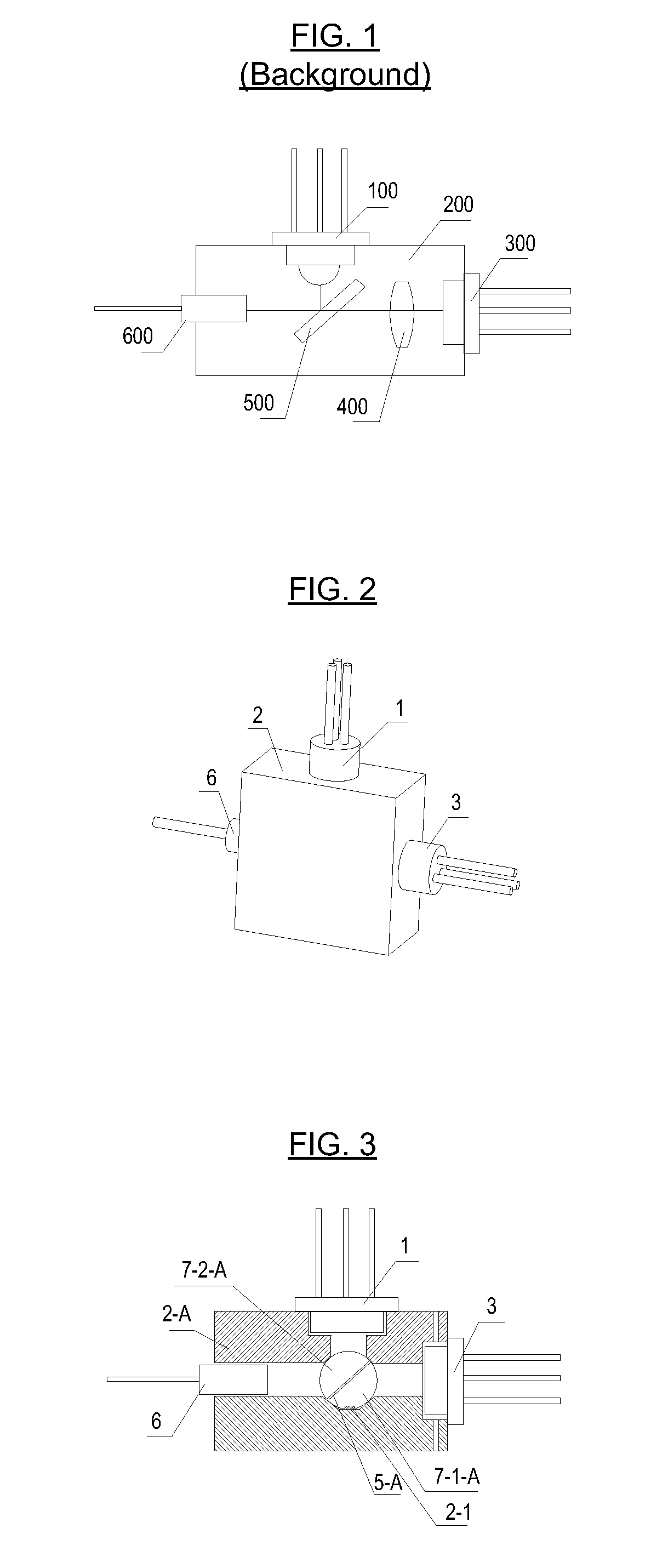
[0087]FIG. 2 generally shows an exterior view of the bi-directional fiber optic transceiver of the present invention, comprising a photodiode 1, a laser diode 3, a fiber 6 and a housing 2. As FIGS. 2 and 3 show, a first embodiment of the bi-directional fiber optic transceiver of the present invention comprises a first hemispherical lens 7-1-A, a second hemispherical lens 7-2-A, and an optical splitter 5-A at a 45-degree angle with regard to the optical path. First hemispherical lens 7-1-A and second hemispherical lens 7-2-A combine to form a spheroid. Laser diode 3 is placed at the focal point of first hemispherical lens 7-1-A, and the photodiode 1 is placed at the focal point of second hemispherical lens 7-2-A. A locating slot 2-1 is below the first hemispherical lens 7-1-A. Housing 2-A for the optical transceiver (see FIGS. 3 and 12) comprises a laser diode mounting hole 2-2, a photodiode mounting hole 2-4, a fiber mounting hole 2-5 and an internal cavity 9-A corresponding to the ...

embodiment ii

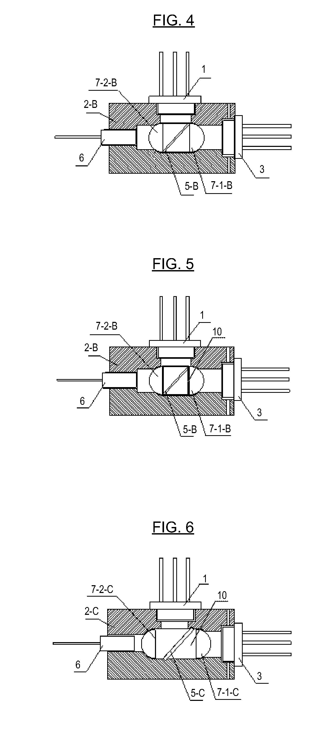
[0089]As FIGS. 2 and 4 show, a second embodiment of the bi-directional fiber optic transceiver of the present invention comprises a first hemispherical lens 7-1-B, a second hemispherical lens 7-2-B, and an optical splitter 5-B that has a 45-degree angle with regard to the optical path. Planar surfaces of the first hemispherical lens 7-1-B and the second hemispherical lens 7-2-B vertically flank the optical splitter 5-B. Ends of the optical splitter 5-B may be adhered to the first hemispherical lens 7-1-B and the second hemispherical lens 7-2-B with an adhesive. The laser diode 3 is placed at the focal point of the first hemispherical lens 7-1-B, and the photodiode 1 is placed at the focal point of second hemispherical lens 7-2-B.

[0090]Housing 2-B of the optical transceiver (FIG. 13) comprises a laser diode mounting hole 2-2, a photodiode mounting hole 2-4 and an internal cavity 9-B corresponding to the optical splitter 5-B and the hemispherical lenses 7-1-B and 7-2-B. Lower walls of...

embodiment iii

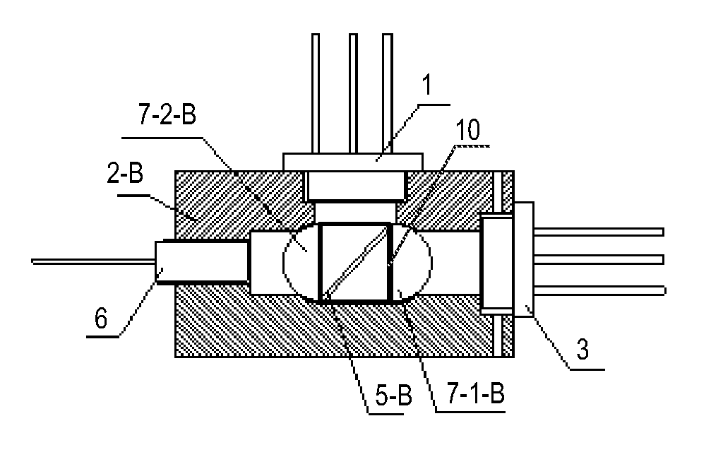
[0091]Referring to FIGS. 2, 5 and 16, a third embodiment of the bi-directional fiber optic transceiver of the present invention comprises a first hemispherical lens 7-1-B, a second hemispherical lenses 7-2-B, and an optical splitter 5-B at a 45-degree angle with regard to the optical path. The flat surfaces of first hemispherical lens 7-1-B and the second hemispherical lens 7-2-B vertically flank the optical splitter 5-B. Ends of the optical splitter 5-B are fixed to the first hemispherical lens 7-1-B and the second hemispherical lens 7-2-B via a rectangular framework (see rectangular framework 10 in FIG. 16), wherein the laser diode 3 is placed at the focal point of the first hemispherical lens 7-1-B, and the optical splitter 5-B is placed at the focal point of the second hemispherical lens 7-2-B.

[0092]Housing 2-B of the optical transceiver (FIG. 13) comprises a laser diode mounting hole 2-2, a photodiode mounting hole 2-4, a fiber mounting hole 2-5 and an internal cavity 9-B corre...


PUM

PropertyMeasurementUnit
angleaaaaaaaaaa
anglesaaaaaaaaaa
anglesaaaaaaaaaa

Abstract

A bi-directional fiber optic transceiver includes a laser diode, a photodiode, first and second lenses, all of which share a common linear optical axis, and a housing. The first lens may have transmission increasing film thereon. The second lens may have a reflection increasing film thereon. An optical splitter may be between the first and second lenses. The first and/or second lenses may be spherical, hemispherical or aspheric. The transceiver size is reduced so that a circuit board can accommodate more components or be smaller in size. Utilizing hemispherical lenses can greatly increase the coupling ratio of the optical links between the photodiode, fiber and laser diode. Utilizing aspheric lenses with high coupling can serve high power output requirements. Use of spherical lenses (which extend the focal length) with aspheric lenses enables LD TO assemblies in individual housings to serve in various products.

Description

CROSS REFERENCE TO RELATED APPLICATIONS[0001]This application claims the benefit of Chinese Patent Application No. 201110177659.0, which was filed on Jun. 29, 2011, Chinese Patent Application No. 201110177660.3, also filed on Jun. 29, 2011, and Chinese Patent Application No. 201110338123.2, which was filed on Oct. 31, 2011, all of which are incorporated by reference as if fully set forth herein.FIELD OF THE INVENTION[0002]The present invention generally relates to optical transceivers, housings therefor and methods of making optical transceivers (e.g., using the housings).DISCUSSION OF THE BACKGROUND[0003]Most conventional communication is enabled via optical fiber or twisted-pair cable. Specifically, communication via optical fiber is characterized by a long transmission distance, low distortion, anti-disturbance, etc., while communication via twisted-pair cable is characterized by simple accessing, good compatibility with other apparatus, etc. Optical fiber transceivers are provid...

Claims


Application Information

Patent Timeline
Patent Type & Authority Applications(United States)
IPC IPC(8): G02B6/36B29C65/48
CPCG02B6/4201G02B6/4246
Inventor CHIU, CHIEN-HSIUNGKO, SHIH-PINCHEN, HUNG-YUAN
Owner SOURCE PHOTONICS
Why Eureka
Try Eureka