
Particle characterisation

a particle and apparatus technology, applied in the field of apparatus for particle characterisation, can solve the problems of large preparation time for potentially few measurements, poor sample quality of light scattering methods for particle characterisation, and dls, and achieve the effects of reducing the noise on the correlogram obtained from the signal, reducing the measurement time, and fast measurement times

Active Publication Date: 2019-03-14
MALVERN INSTRUMENTS
View PDF24 Cites 7 Cited by
  • Summary
  • Abstract
  • Description
  • Claims
  • Application Information

AI Technical Summary

Benefits of technology

The patent is about a detection system that can measure multiple points quickly. This is possible because the system has multiple detection points, which means it can measure multiple things at once. The system uses a special lens that efficiently collects and focuses light from the detection area. The patent describes how this system could be used to measure scattered light in a way that is faster and more accurate than other methods. By using multiple detection points, the system can measure more than one point at once, which makes the measurement faster. This advantage makes it possible to measure things very quickly.

Problems solved by technology

Light scattering methods for particle characterisation, particularly dynamic light scattering (DLS), have long been criticised for susceptibility to poor sample quality due to the R6 dependency of the strength of the scattered light (for a particle of radius R).
This dependency means that tiny fractions of aggregated material, commonly found and of interest in pharmaceutical applications, dominate the measurement, with an attendant reduction in the accuracy of the size measurement of the much smaller, more weakly scattering fraction.
As such, using DLS requires a large amount of preparation time for potentially few measurements.

Method used


Image

  • Particle characterisation
  • Particle characterisation
  • Particle characterisation

Examples


Embodiment Construction

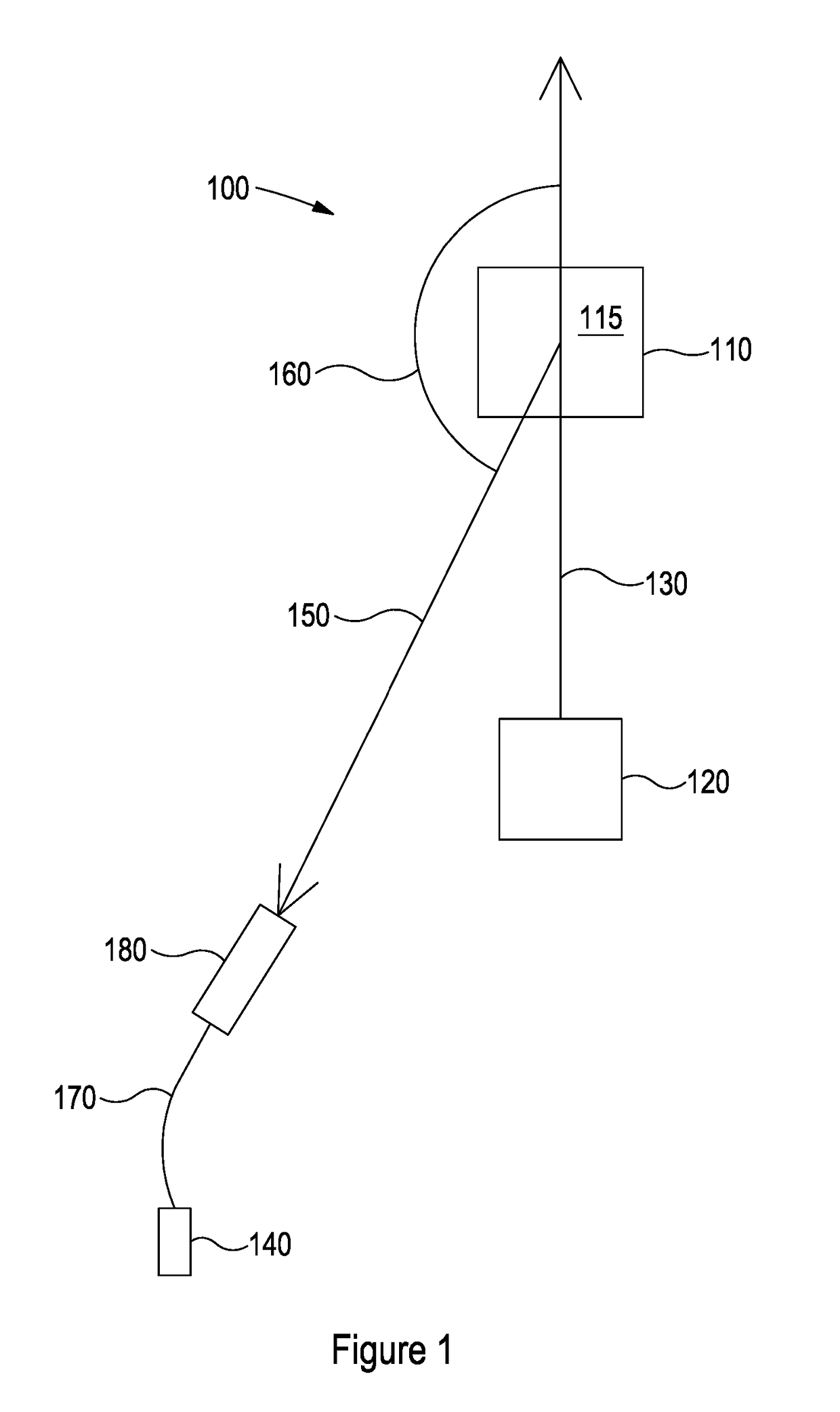
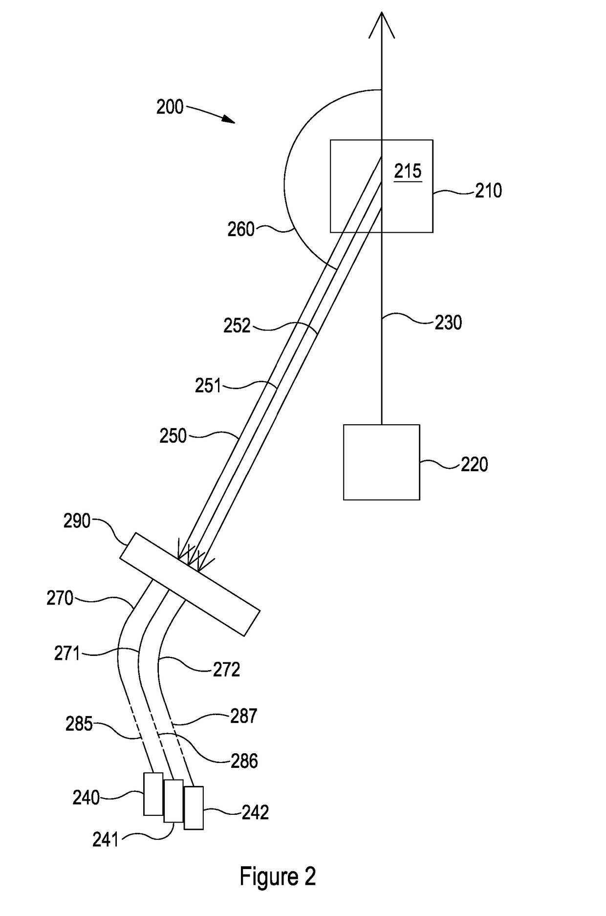
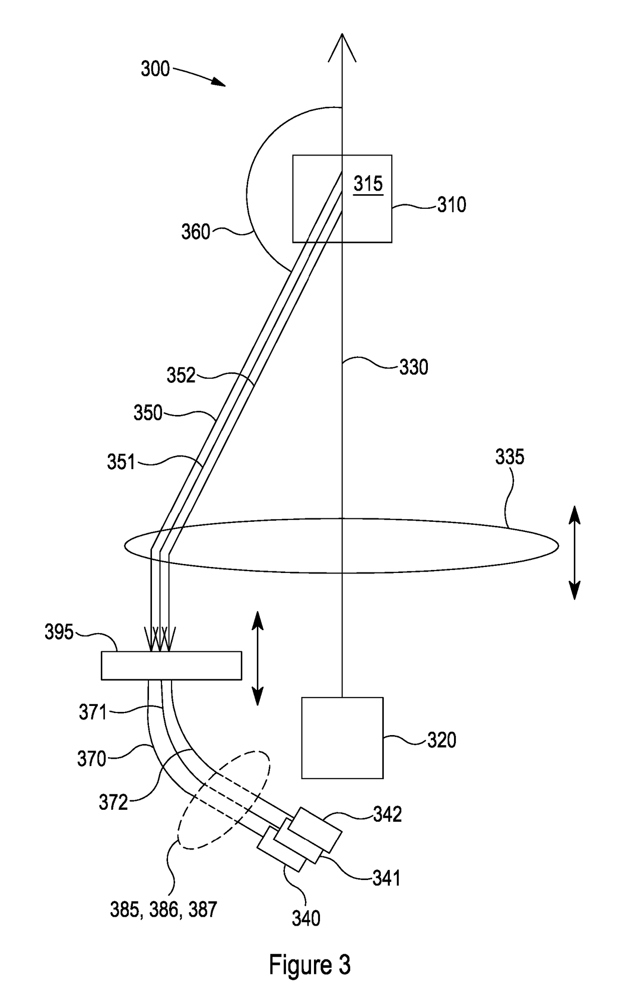
[0062]In the following description, similar reference signs are generally used to refer to corresponding or similar features in different embodiments, where the first digit is incremented to correspond to the figure in question (e.g. 110 and 210 correspond to a sample cell in FIGS. 1 and 2 respectively). In this disclosure, the term “back scattered light” refers to scattered light having a component of propagation direction that is opposite to the direction of propagation of the illumination beam, the term “forward scattered light” refers to scattered light having a component of propagation direction in the same direction as the propagation direction of the illumination beam, and “side scattered light” refers to light scattered in a direction perpendicular to the propagation direction of the illumination beam.

[0063]Referring to FIG. 1, a prior art light scattering particle characterisation apparatus 100 is shown, in which a light source 120 illuminates a sample 115 within a sample c...


PUM

PropertyMeasurementUnit
diameteraaaaaaaaaa
acute angle scatteringaaaaaaaaaa
angleaaaaaaaaaa

Abstract

An apparatus for particle characterisation, comprising: a sample cell for holding a sample; a light source configured to illuminate the sample with an illuminating beam and a plurality of light detectors, each light detector configured to receive scattered light resulting from the interaction between the illuminating beam and the sample along a respective detector path, wherein each respective detector path is at substantially the same angle to the illuminating beam.

Description

CROSS-REFERENCE TO RELATED APPLICATIONS[0001]This application is a national stage application under 35 USC 371 of International Application No. PCT / GB2017 / 050733 filed Mar. 16, 2017, which claims the priority of GB Application No. 1604460.4, filed Mar. 16, 2016, the entire contents of which are incorporated herein by reference.FIELD OF THE INVENTION[0002]The present invention relates to an apparatus for particle characterisation.BACKGROUND OF THE INVENTION[0003]Light scattering methods for particle characterisation, particularly dynamic light scattering (DLS), have long been criticised for susceptibility to poor sample quality due to the R6 dependency of the strength of the scattered light (for a particle of radius R). This dependency means that tiny fractions of aggregated material, commonly found and of interest in pharmaceutical applications, dominate the measurement, with an attendant reduction in the accuracy of the size measurement of the much smaller, more weakly scattering f...

Claims


Application Information

Patent Timeline
Patent Type & Authority Applications(United States)
IPC IPC(8): G01N15/02
CPCG01N15/0211G01N2015/0222G01N2015/035G01N15/0205G01N21/49G01N21/01G01N2021/4719
Inventor CORBETT, JASON
Owner MALVERN INSTRUMENTS
Learn More