Optical module including an optoelectronic device

an optoelectronic device and optical module technology, applied in the field of optical modules, can solve the problems of poor coupling efficiency, high accuracy, and significant influence on the cost of production of optical apparatuses, and achieve the effect of high coupling efficiency

Active Publication Date: 2007-05-29
STMICROELECTRONICS SRL
View PDF6 Cites 7 Cited by
  • Summary
  • Abstract
  • Description
  • Claims
  • Application Information

AI Technical Summary

Benefits of technology

[0007]An object of the present invention is to provide an optical module that provides a high coupling efficiency without requiring complex alignment techniques of the optical components.

Problems solved by technology

This accuracy significantly affects the cost of production of an optical apparatus.
Conventional optical modules have the drawback of being relatively expensive and offering poor coupling efficiency unless complex techniques of alignment of the optical components are used.

Method used


Image

  • Optical module including an optoelectronic device
  • Optical module including an optoelectronic device
  • Optical module including an optoelectronic device

Examples


first embodiment

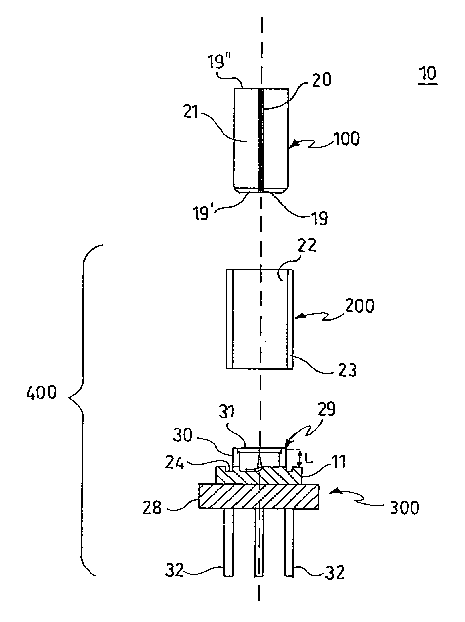
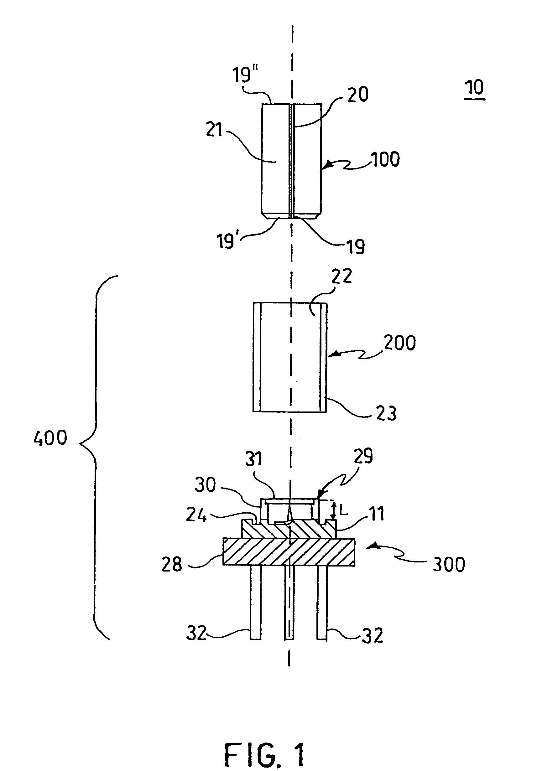
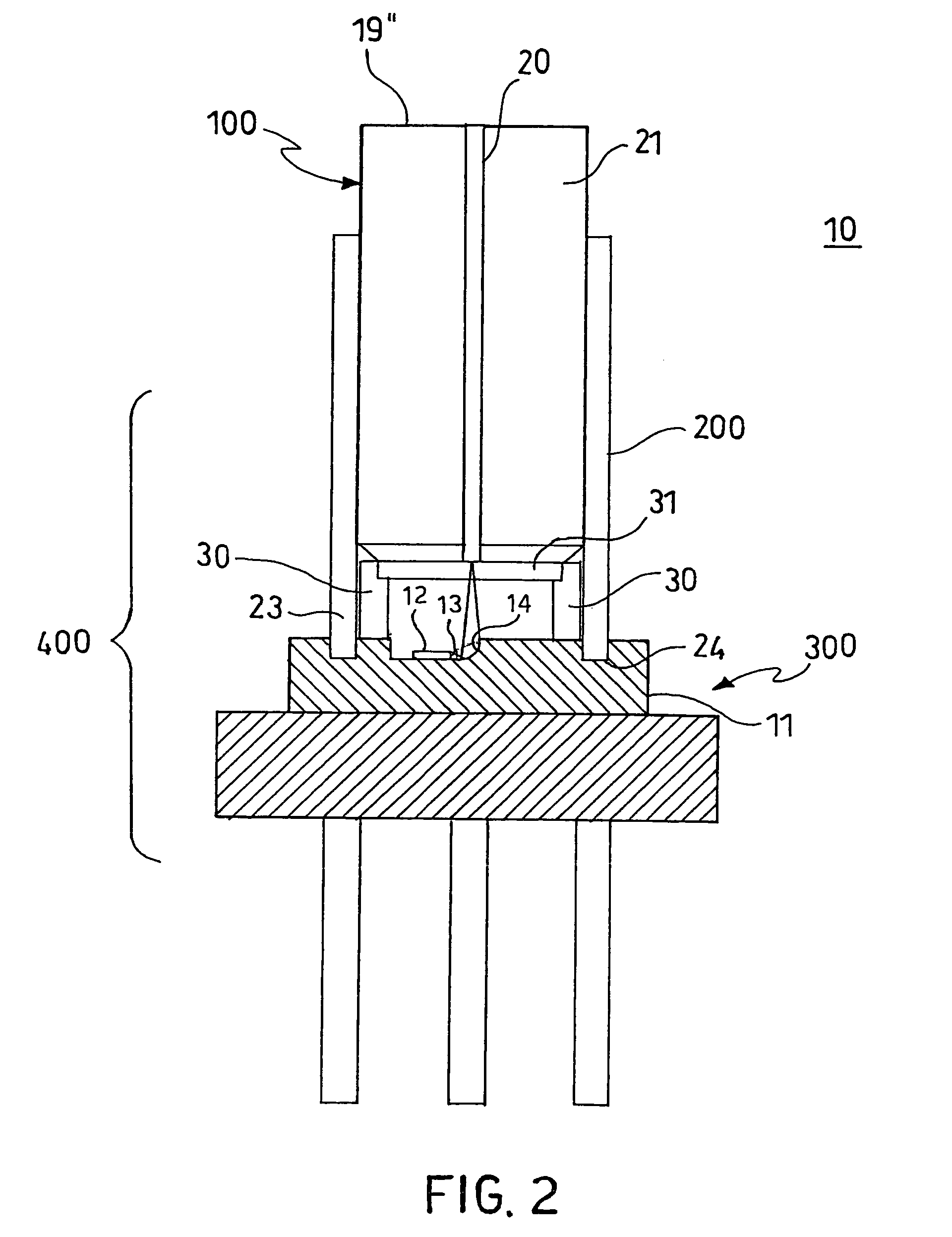
[0025]FIGS. 1 and 2 show an optical apparatus 10 in accordance with the invention. The optical apparatus 10 comprises an optical module 400 and means 100 of guided propagation of electromagnetic radiation. The optical module 400 includes an optoelectronic module or unit 300 optionally provided with a structure 200 for positioning the propagation means 100. It is possible to supply the optoelectronic unit 300 alone, i.e., not coupled to the support structure 200 and without with propagation means 100. Alternatively, the optoelectronic unit 300 is coupled to the support structure 200 and may or may not be provided with the propagation means 100.

[0026]In greater detail, the propagation means 100 include an optical wave guide such as, preferably, an optical fiber 20 and a ferrule or bushing 21 that at least partially houses the optical fiber itself.

[0027]The optical fiber 20 is, for example, any conventional type fiber (monomodal or multimodal) and comprises a mantle, a nucleus or core ...

second embodiment

[0067]In accordance with the invention, the optoelectronic device 12 is not a laser but is a photodetector or photoreceptor that can be applied, for example, to the bottom wall 26 in the same way as for the laser 12.

[0068]A photodetector suitable for being used in the apparatus of the invention is the detector known as a pin detector. A photodetector of this type is marketed, for example, by Honeywell.

[0069]This type of photodetector presents a substantially parallelepiped form and is provided with a portion to receive the optical radiation positioned on a lateral face of the parallelepiped. The face of the photodetector can be oriented in exactly the same way as shown in FIGS. 1–3 for the laser 12, in order to receive the radiation reflected by the reflection and focusing device 14. The functioning of the apparatus 10 in the presence of the photodetector 12 is obvious to those skilled in the art.

[0070]Advantageously, according to another embodiment, the reflective wall 15 defines a...


PUM


Abstract

An optical module includes a support substrate, and an optoelectronic device on the support substrate. A coupling device provides optical coupling of the optoelectronic device with an optical fiber. The coupling device is integrated in the substrate, and is a reflection device inserted into an optical path between the optoelectronic device and the optical fiber.

Description

FIELD OF THE INVENTION[0001]The present invention relates to an optical module that can be used for coupling an optoelectronic device to an optical fiber.BACKGROUND OF THE INVENTION[0002]Many modules for coupling a laser diode or a photodetector to a wave guide, for example, are known, either in the form of conventional type optical fiber or in the form of integrated wave guides. In general, the coupling of optical components is a critical aspect in the design of optical apparatus because, in numerous applications, there is a requirement to ensure a high efficiency of coupling to allow optimum transfer of the radiation between the components themselves.[0003]To obtain a high efficiency, due to the typical dimensions in question (on the order of a tenth of a micron), considerable accuracy is required in the mutual alignment and positioning between the devices to be coupled. This accuracy significantly affects the cost of production of an optical apparatus.[0004]On this subject, U.S. ...

Claims


Application Information

Patent Timeline
Patent Type & Authority Patents(United States)
IPC IPC(8): G02B6/36G02B6/42
CPCG02B6/4214G02B6/4292
Inventor FINCATO, ANTONIO
Owner STMICROELECTRONICS SRL
Why Eureka
Try Eureka