Fiber optic rotary joints and methods of using and manufacturing same

Active Publication Date: 2018-12-06
CANON USA
View PDF4 Cites 7 Cited by
  • Summary
  • Abstract
  • Description
  • Claims
  • Application Information

AI Technical Summary

Benefits of technology

[0010]Accordingly, it is a broad object of the present disclosure to provide fiber optic rotary joints that may be used with one or more optical apparatuses, systems, methods (for using and/or manufacturing) and storage mediums, such as, but not limited to, fiber optic catheters, endoscopes and/or optical coherence tomography (OCT) apparatuses and systems, and methods and storage mediums, for use with same, to achieve structural compactness and

Problems solved by technology

Further, the detected light may be collected in the same or in one or more additional fibers, and, if rotating, these additional fibers may structurally interfere with each other.
It is difficult to make collimated beams for the common rotor fibers with different wavelengths, especially when the wavelength differences are large (e.g., in the range of 630 nm to 1300 nm, about

Method used


Image

  • Fiber optic rotary joints and methods of using and manufacturing same
  • Fiber optic rotary joints and methods of using and manufacturing same
  • Fiber optic rotary joints and methods of using and manufacturing same

Examples


Embodiment Construction

[0029]One or more devices, optical systems, methods and storage mediums for imaging using a fiber optic rotary joint, and one or more methods of manufacturing at least one fiber optic rotary joint and / or of manufacturing at least one free space optical beam combiner, are disclosed herein.

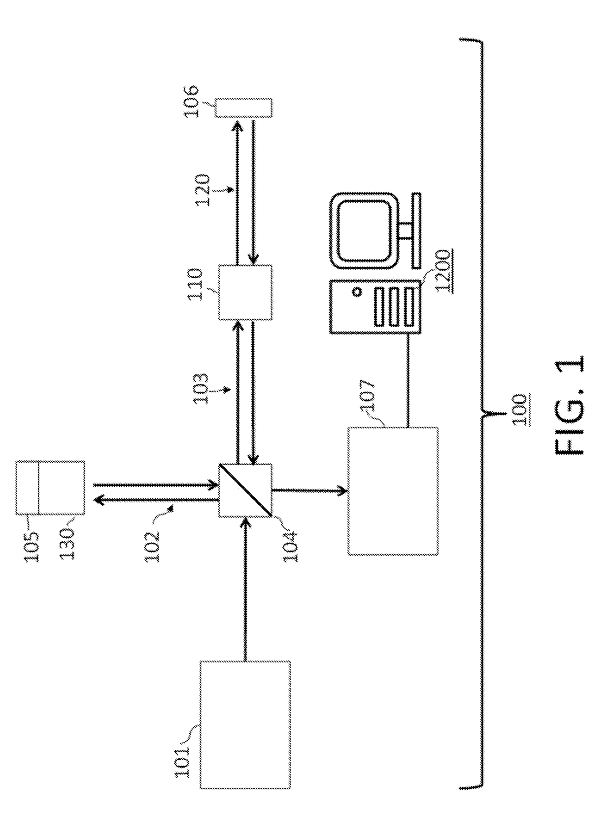
[0030]Turning now to the details of the figures, FIG. 1 shows an OCT system 100 (as referred to herein as “system 100” or “the system 100”) which operates to utilize an OCT technique with optical probe applications in accordance with one or more aspects of the present disclosure. The system 100 comprises a light source lot, a reference arm 102, a sample arm 103, a splitter 104 (also referred to herein as a “beam splitter”), a reference mirror (also referred to herein as a “reference reflection”) 105, and one or more detectors 107. The system 100 may include a phase shift device or unit 130. In one or more embodiments, the system 100 may include a patient interface device or unit (“PIU”) 110 and a ca...


PUM


Abstract

One or more fiber optic rotary joints (FORJ), free space beam combiners, OCT, SEE and/or fluorescence devices and systems for use therewith, methods of manufacturing same and storage mediums are provided. One or more embodiments of FORJs may be used with numerous applications in the optical field, including, but not limited to, OCT and fluorescence applications. Examples of such applications include imaging, evaluating and diagnosing biological objects, such as, but not limited to, for Gastro-intestinal, cardio and/or ophthalmic applications, and being obtained via one or more optical instruments.

Description

CROSS-REFERENCE TO RELATED APPLICATION(S)[0001]This application relates, and claims priority, to U.S. Patent Application Ser. No. 62 / 513,829, filed Jun. 1, 2017, the entire disclosure of which is incorporated by reference herein in its entirety.FIELD OF THE INVENTION[0002]The present disclosure relates generally to the field of optical imaging and more particularly to fiber optic rotary joints that may be used with one or more optical apparatuses, systems, methods (for using and / or manufacturing) and storage mediums, such as, but not limited to, fiber optic catheters, endoscopes and / or optical coherence tomography (OCT) and / or fluorescence apparatuses and systems, and methods and storage mediums, for use with same, to achieve structural compactness and high coupling efficiency. Examples of optical applications that may involve the use of a fiber optic rotary joint include imaging, evaluating and characterizing / identifying biological objects or tissue, such as, but not limited to, fo...

Claims


Application Information

Patent Timeline
IPC IPC(8): G02B6/36G01B9/02
CPCG02B6/3604G01B9/02091A61B5/0035A61B5/0066A61B5/0071A61B5/6852G02B6/29362G02B6/32
Inventor YAMADA, DAISUKE
Owner CANON USA
Why Eureka
Try Eureka