Perimeter clip for seismic ceilings

a seismic ceiling and clip technology, applied in the field of ceilings, can solve the problems of visually incompatible with the rest of the grid ceiling, two inch wide ledges,

Active Publication Date: 2007-11-13
3DXLP LLC +1
View PDF14 Cites 81 Cited by
  • Summary
  • Abstract
  • Description
  • Claims
  • Application Information

AI Technical Summary

Benefits of technology

[0009]The new use of the modified '294 clip eliminates, in a suspended ceiling subject to seismic forces, the need for a 2 inch wide horizontal ledge on the angle wall molding that supports the ends of the grid beams. The invention permits the use, in such a ceiling, of a wall molding ledge of about ⅞ inch, as is now used in non-seismic ceilings, that is usually compatible with, and in harmony with, the beam flanges, which are visible from below.
[0018]The leg of the clip, in which the end of the beam slides during a quake, has a continuous slot that, from the beam rest position, toward the wall, is horizontal, and away from the wall, is inclined. A self-tapping screw is passed through the slot and the beam, piercing the end of a beam, at a right angle thereto. The screw, which acts as movable pin, rides in the slot, and lifts the beam end above the ledge as the beam moves away from the wall during a quake. As the beam moves back toward the wall, in its reciprocating movement during a quake, the beam end clears the edge of the ledge of the wall molding, so there is no interference between the beam end and the edge of the wall molding ledge.

Problems solved by technology

Such a two inch wide ledge, however, is visually incompatible with the rest of the grid ceiling, when viewed from below, since the flanges on the beam are generally less than 1 inch wide.

Method used


Image

  • Perimeter clip for seismic ceilings
  • Perimeter clip for seismic ceilings
  • Perimeter clip for seismic ceilings

Examples


Embodiment Construction

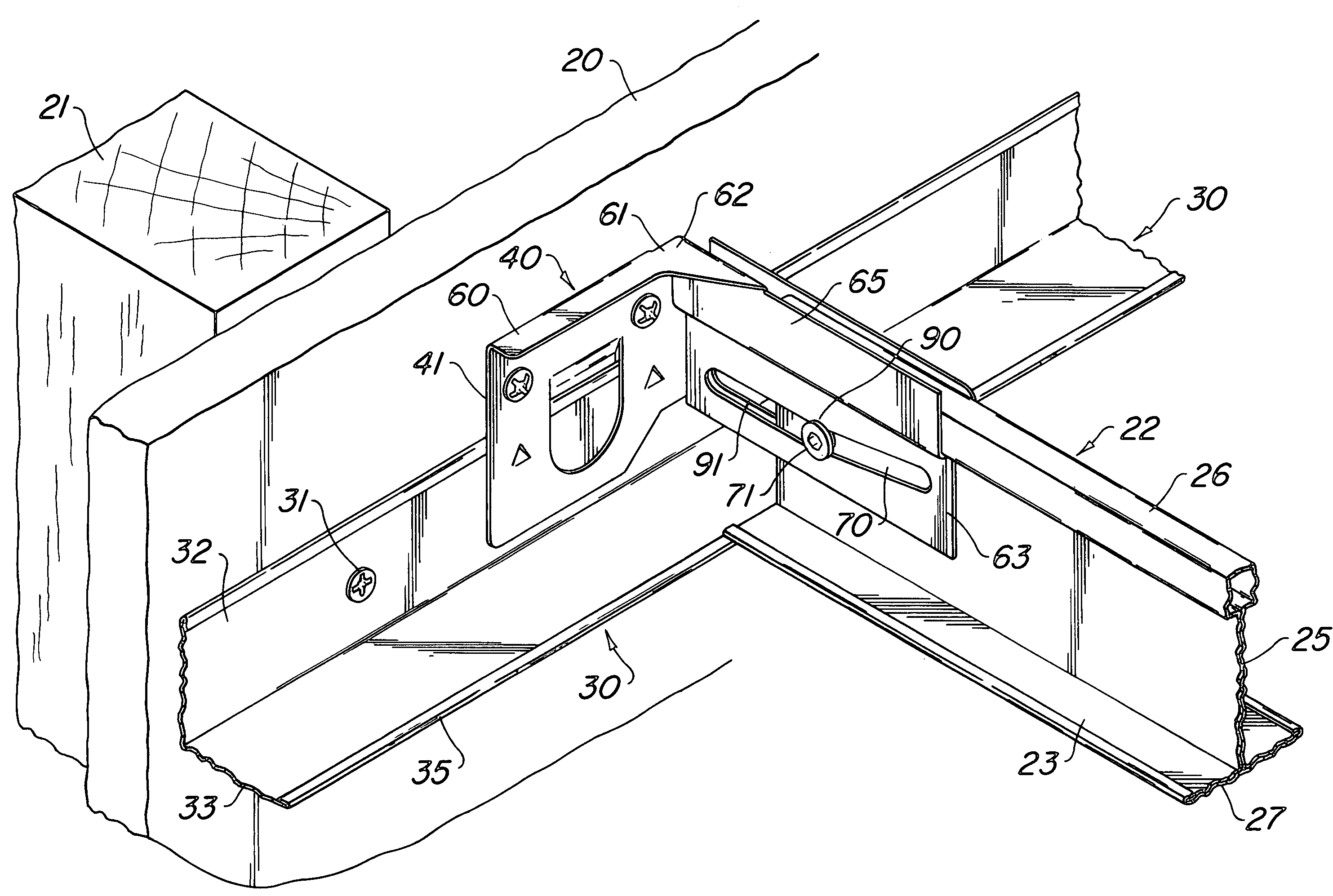
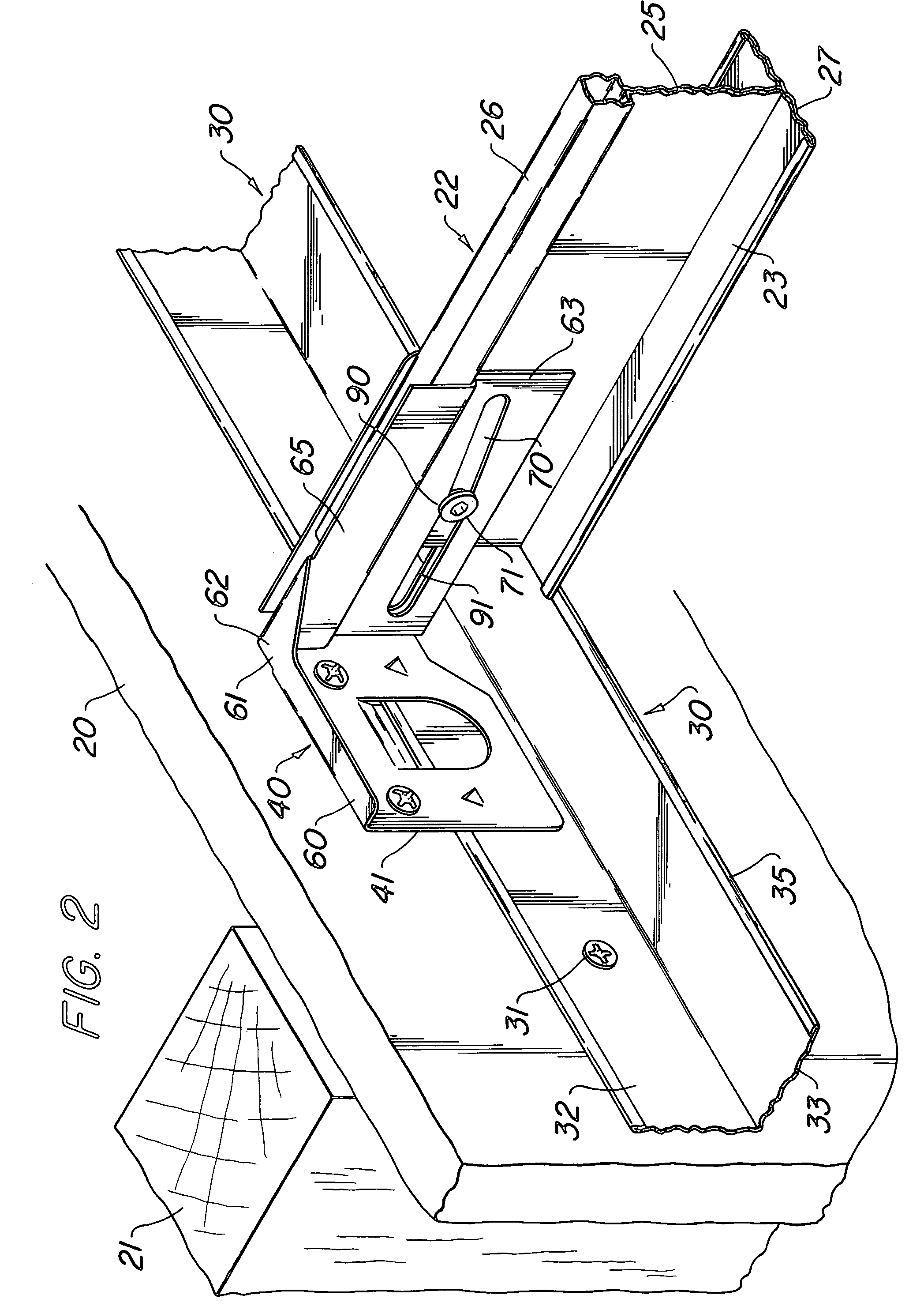
[0025]As seen in FIG. 2, a vertical dry, or plastered, wall 20 is supported from a wood post structure 21. The wall 20 forms one side of a room within a building and generally extends from the floor to a structural ceiling.

[0026]A suspended ceiling of the grid type as shown, for instance, in the '681 patent referred to above, has a beam 22 in the form of an inverted T. Beam 22 integrally has a flange 23, a web 25, and a bulb 26. Beam 22 is roll formed from a longitudinally extending flat strip bent to form the beam elements. A cover piece 27 is wrapped around the flange 23 of the beam and is painted a desired color. Such beams 22 are well known in the art and are interconnected to form the grid structure for the panels that are laid in the grids.

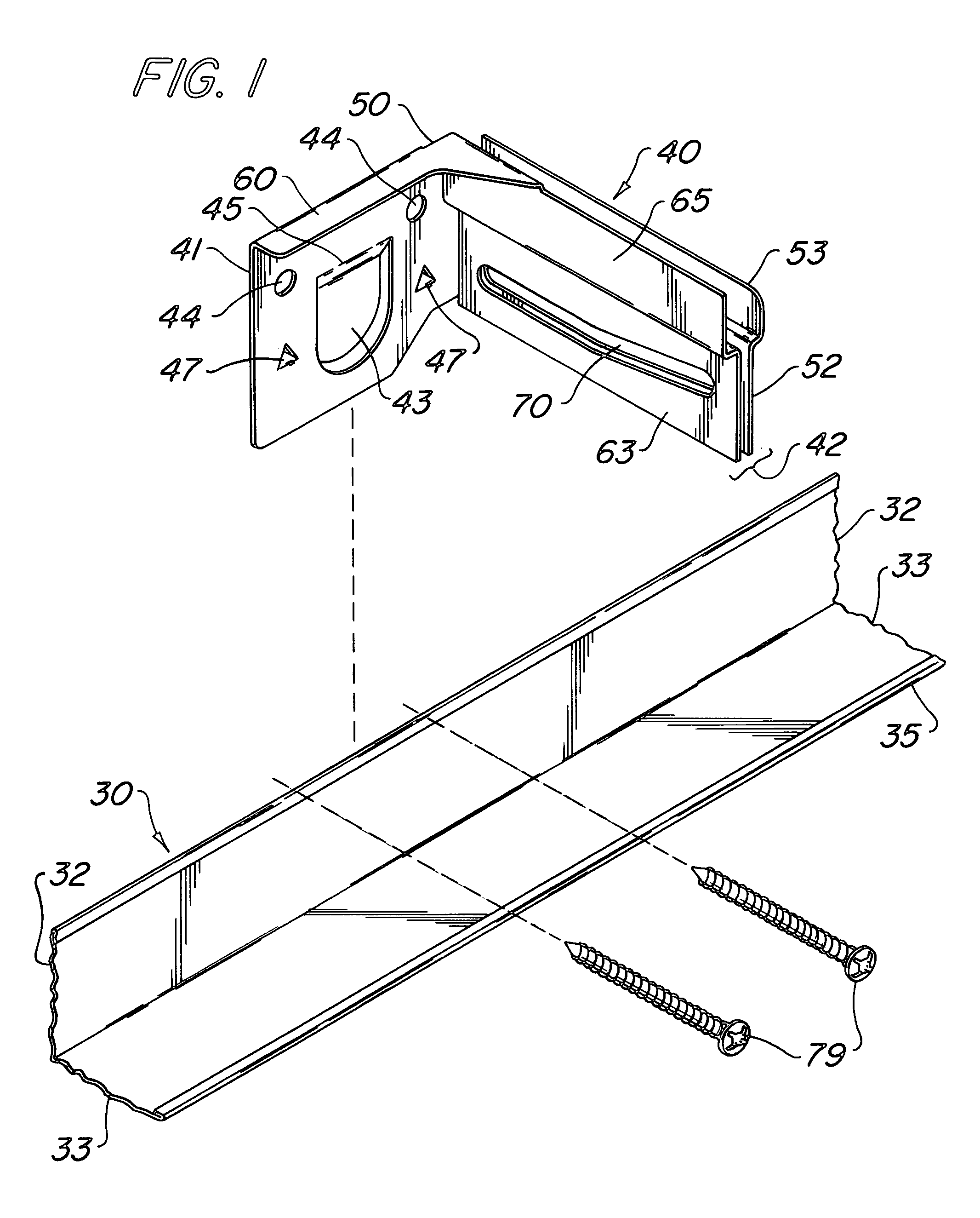
[0027]An angle wall molding 30 is secured to wall 20 by screws or fasteners 31. The wall molding 30 extends horizontally along the wall 20 at the desired suspended ceiling height. Wall molding 30 forms an angle in cross section having a wall...


PUM


Abstract

A perimeter clip attached to a wall molding that supports a beam in a suspended ceiling intended to survive seismic disturbances. The clip is capable, during an earthquake, of permitting an end of a beam at one end of a connected line of beams, in a grid, to slide while being supported in the clip, or, in the alternative, to secure an end of a beam to the wall molding.

Description

BACKGROUND OF THE INVENTION[0001](1) Field of the Invention[0002]The invention relates to ceilings capable of surviving seismic disturbances. The ceilings are of the suspended type that have a grid of interconnected metal beams hung from a structural ceiling. Panels are supported in the grid openings.[0003](2) Description of the Related Art[0004]Suspended ceilings have a grid of beams hung from a structural ceiling by wires. Panels are supported in the grid openings. An angle wall molding runs around the perimeter of the ceiling and supports the ends of the grid beams. Such a ceiling is shown in U.S. Pat. No. 4,827,681, incorporated herein by reference.[0005]The beams are roll formed of strip steel bent, in cross section, into a vertically extending web, horizontally extending flanges at the bottom of the web, and a bulb at the top of the web. The beams are interconnected into a grid. The grid is hung with wires from the structural ceiling, within the vertical walls of the individua...

Claims


Application Information

Patent Timeline
Patent Type & Authority Patents(United States)
IPC IPC(8): E04C2/42E04B9/00E04B1/38E04B2/00E04B9/08E04B9/16E04B9/30
CPCE04B9/067E04B9/30E04B9/08
Inventor KELLY, JOSEPH J.PLATT, WILLIAM J.
Owner 3DXLP LLC
Why Eureka
Try Eureka