Framing system

a framing system and frame wall technology, applied in the direction of girders, joists, trusses, etc., can solve the problems of affecting the material flow the inability to apply tension straps to the outside of the framed wall, and the inability to meet the requirements of plywood in the first method

Active Publication Date: 2007-11-27
HILDRETH JOHN
View PDF10 Cites 47 Cited by
  • Summary
  • Abstract
  • Description
  • Claims
  • Application Information

AI Technical Summary

Problems solved by technology

The requirement for a strong panel material such as plywood in the first method is undesirable because these panel materials cost more than alternative, lower strength panel materials.
The second method of applying tension straps to the outside of the framed wall is undesirable for at least two reasons.
First, applying tension straps on the exterior (either the inward or outward facing side) of a framed wall interferes with materials (e.g., drywall or plywood) placed over the straps.
Second, installing the straps can be problematic.
On the one hand, if the straps are installed before the wall is in place, the wall cannot be adjusted to account for on-site conditions.
This results in a fairly large displacement before the straps have any effect, thereby decreasing the effectiveness of the straps.

Method used


Image

  • Framing system
  • Framing system
  • Framing system

Examples


Embodiment Construction

[0017]The present invention will be discussed with reference to preferred embodiments of light gauge framed shear walls. Specific details are set forth in order to provide a thorough understanding of the present invention. The preferred embodiments discussed herein should not be understood to limit the invention. Furthermore, for ease of understanding, certain method steps are delineated as separate steps; however, these steps should not be construed as necessarily distinct nor order dependent in their performance.

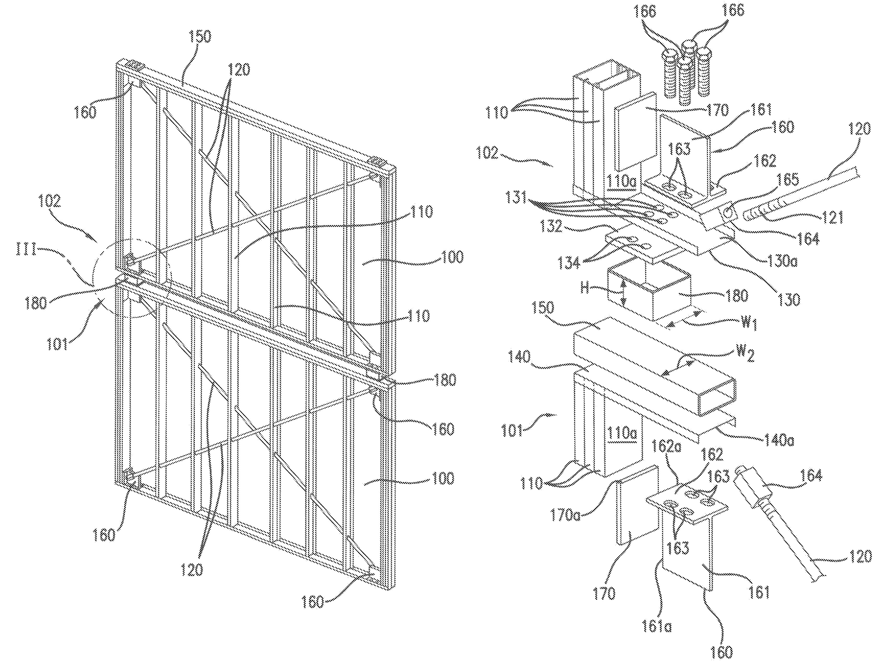
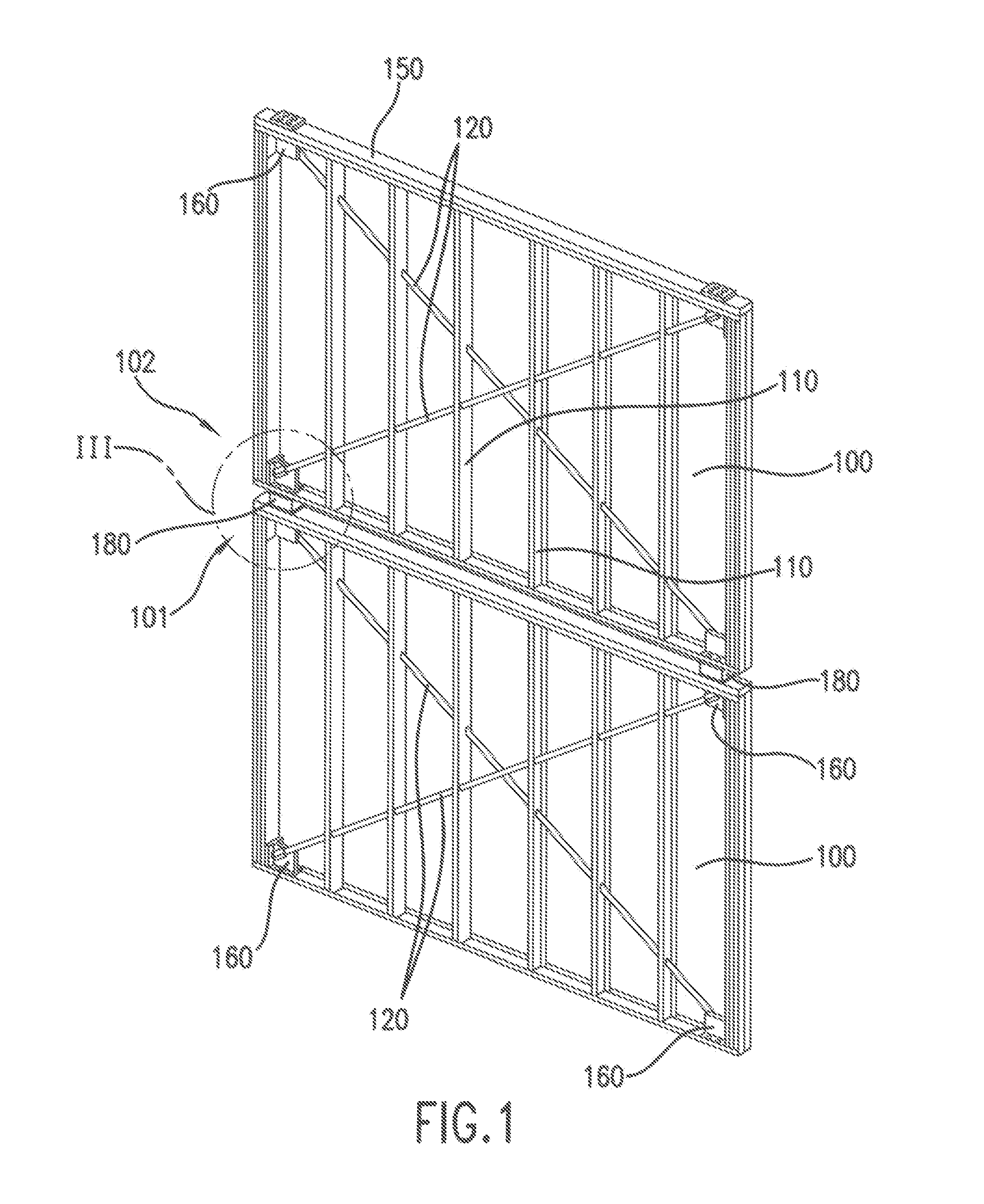
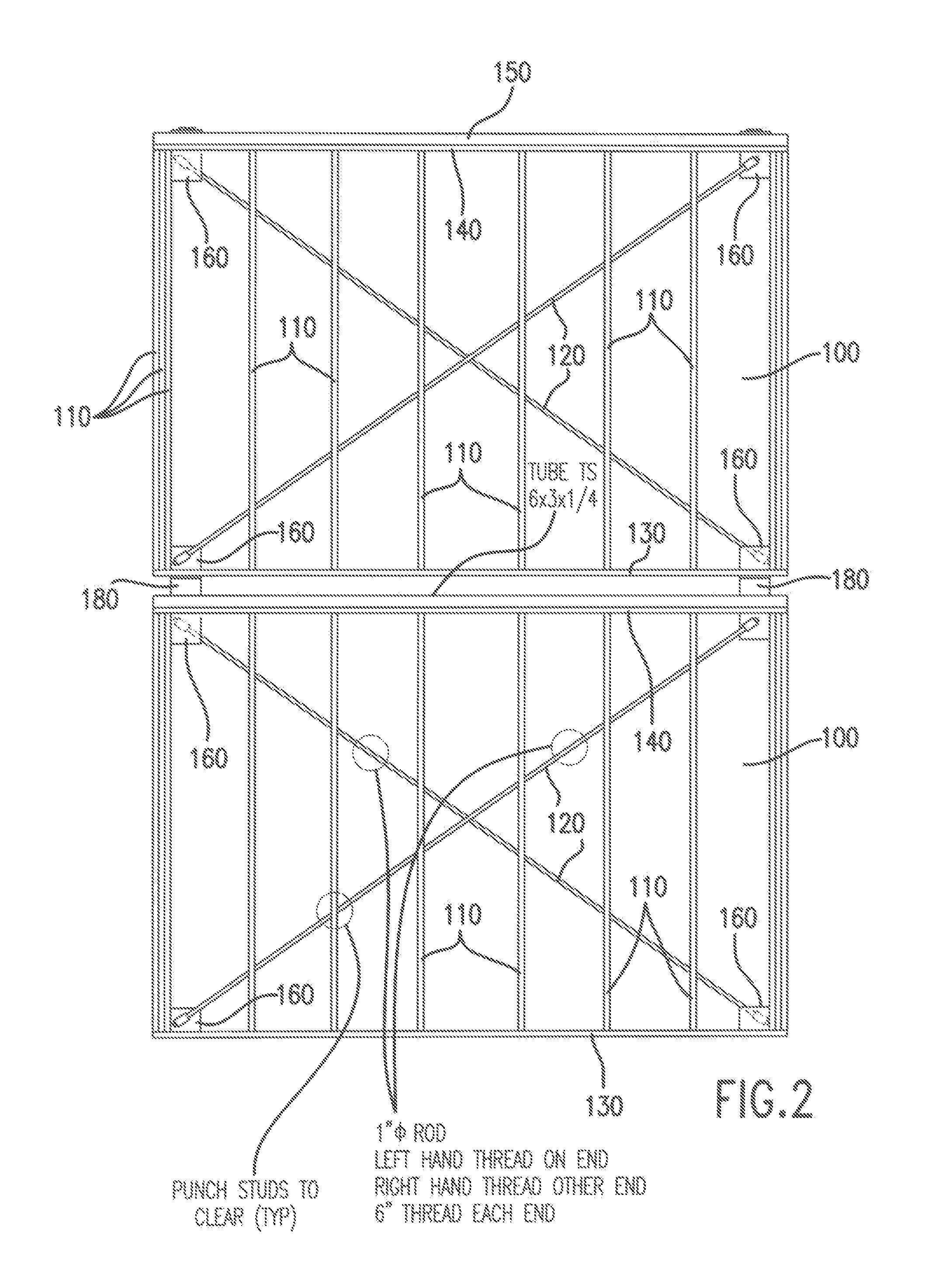
[0018]FIG. 1 is a perspective view and FIG. 2 is a side view of two attached shear walls 100 according to a preferred embodiment of the present invention. Each of the shear walls 100 comprises a plurality of vertically oriented, spaced-apart studs 110. Three studs 110 are ganged together at the sides of each of the walls 100 for added strength. The studs 110 are connected by a bottom channel 130 and a top channel 140. A hollow rectangular member 150 is installed on the top...


PUM


Abstract

A framed shear wall has a pair of crossed tension straps passing through the studs that make up the shear wall. The straps are preferably rods and are preferably attached to upstanding plates installed at the corners of the wall. Each of two straps is preferably attached to an opposite side of the upstanding plate such that the straps do not interfere with each other where the straps cross. The straps preferably include threaded ends and the upstanding plates preferably have threaded receptacles sized to accept the threaded ends of the straps such that the straps can be tensioned before and / or after installation. In one embodiment, the upstanding plates are bolted through a bottom surface of the wall into a threaded anchor plate at floor level, and the threaded anchor plate is attached to a top of a wall on a floor below.

Description

BACKGROUND OF THE INVENTION[0001]1. Field of the Invention[0002]The invention relates to framing systems generally, and more particularly to light gauge framing systems.[0003]2. Discussion of the Background[0004]Light gauge framing, especially light gauge steel framing, is becoming an increasingly popular alternative to wood framing in both residential and commercial construction. Structures built with light gauge framing, like other structures, must resist natural forces such as windstorms and earthquakes. “Shear elements” is the name given to elements of the structure that resist these forces. In light gauge framing, the shear elements are typically shear walls.[0005]Shear walls are typically constructed by either 1) applying a strong panel product such as plywood on the outside of a wall framed with light gauge elements, or 2) applying a tension strap to the outside of such a light gauge framed wall (as used herein, “framed wall” refers to a wall constructed with spaced-apart stu...

Claims


Application Information

Patent Timeline
Patent Type & Authority Patents(United States)
IPC IPC(8): E04C3/02E04B1/00E04B1/24E04H9/02
CPCE04B1/24E04H9/028E04B2001/2496E04B2001/2415E04H9/0237
Inventor HILDRETH, JOHN
Owner HILDRETH JOHN
Why Eureka
Try Eureka