Stent embolization device

a technology of embolization device and stent, which is applied in the field of new devices for treating the vessel of a patient, can solve the problems of serious problems and occlusion of the parent vessel

Inactive Publication Date: 2007-12-11
CODMAN & SHURTLEFF INC
View PDF42 Cites 111 Cited by
  • Summary
  • Abstract
  • Description
  • Claims
  • Application Information

AI Technical Summary

Benefits of technology

[0006]In the illustrative embodiment of the invention, the embolization element comprises a collapsible framework supporting a mesh or membrane. The mesh or membrane comprises a biocompatible material from the group consisting of PVA, PVP and collagen. The embolization element is generally cup-shaped and has a cross sectional area that, when introduced into an aneurysm or a vessel, reduces or restricts blood flow into the aneurysm or vessel.

Problems solved by technology

In wider neck aneurysms, it has been found that the embolic coils tend to migrate back to the parent vessel, which may result in occlusion of the parent vessel.
Further, migration of the coil or coils back into the parent vessel may cause the coil or coils to be moved by the blood into another portion of the vessel, creating potentially serious problems.

Method used


Image

  • Stent embolization device
  • Stent embolization device
  • Stent embolization device

Examples


Embodiment Construction

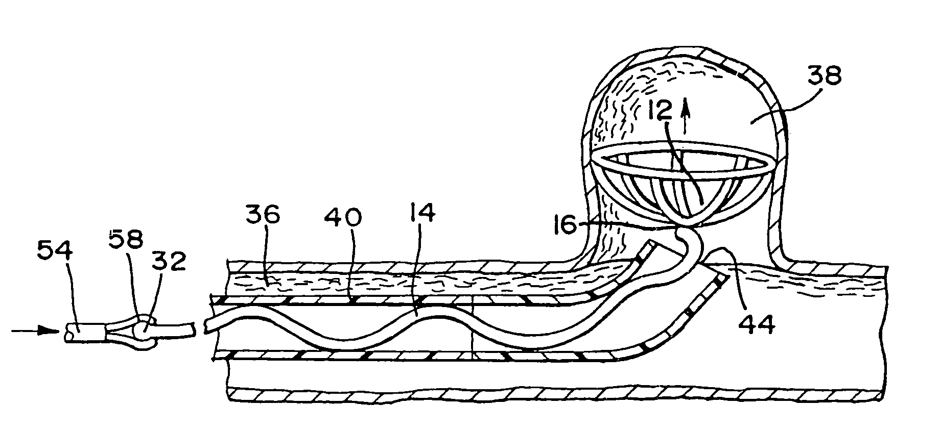
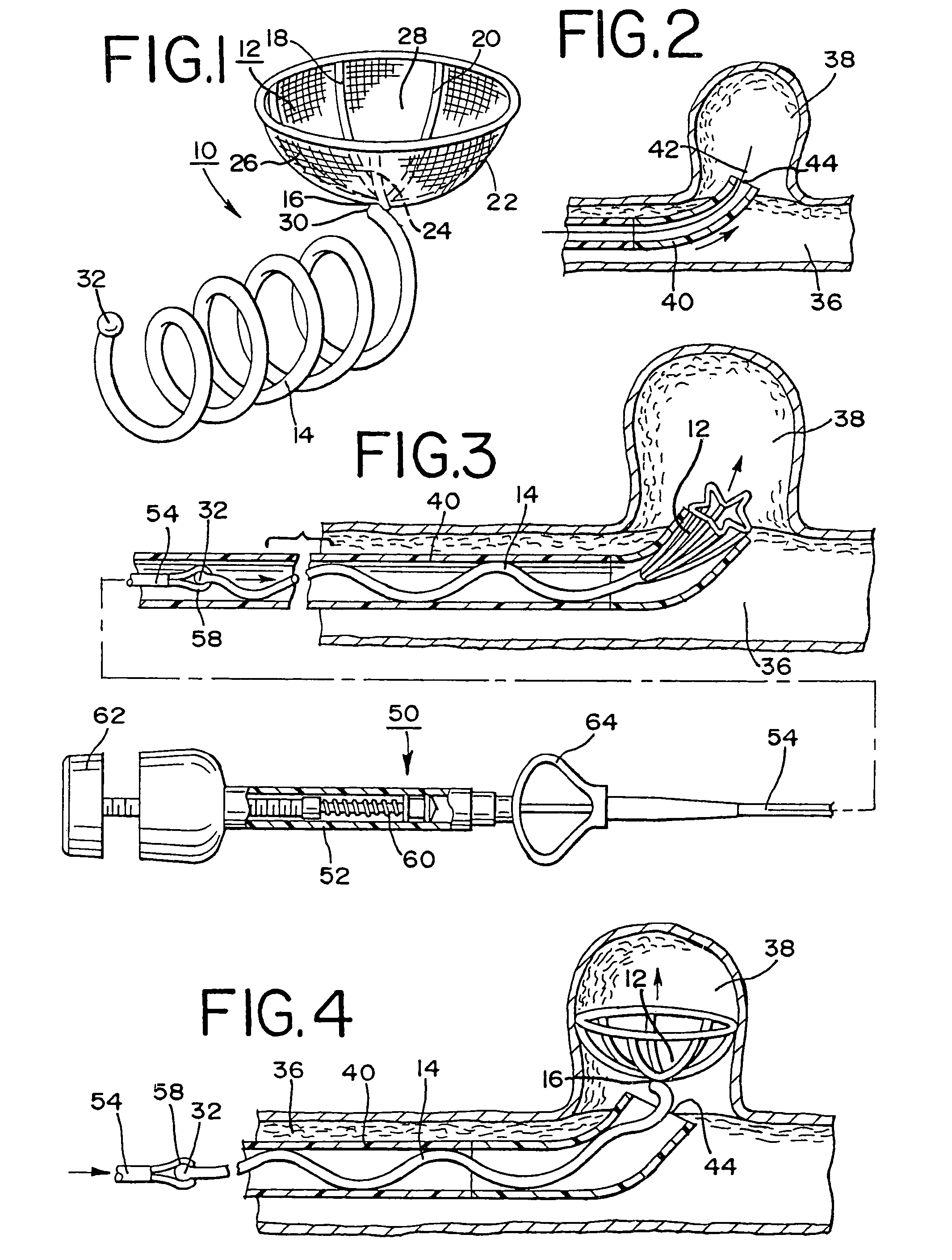
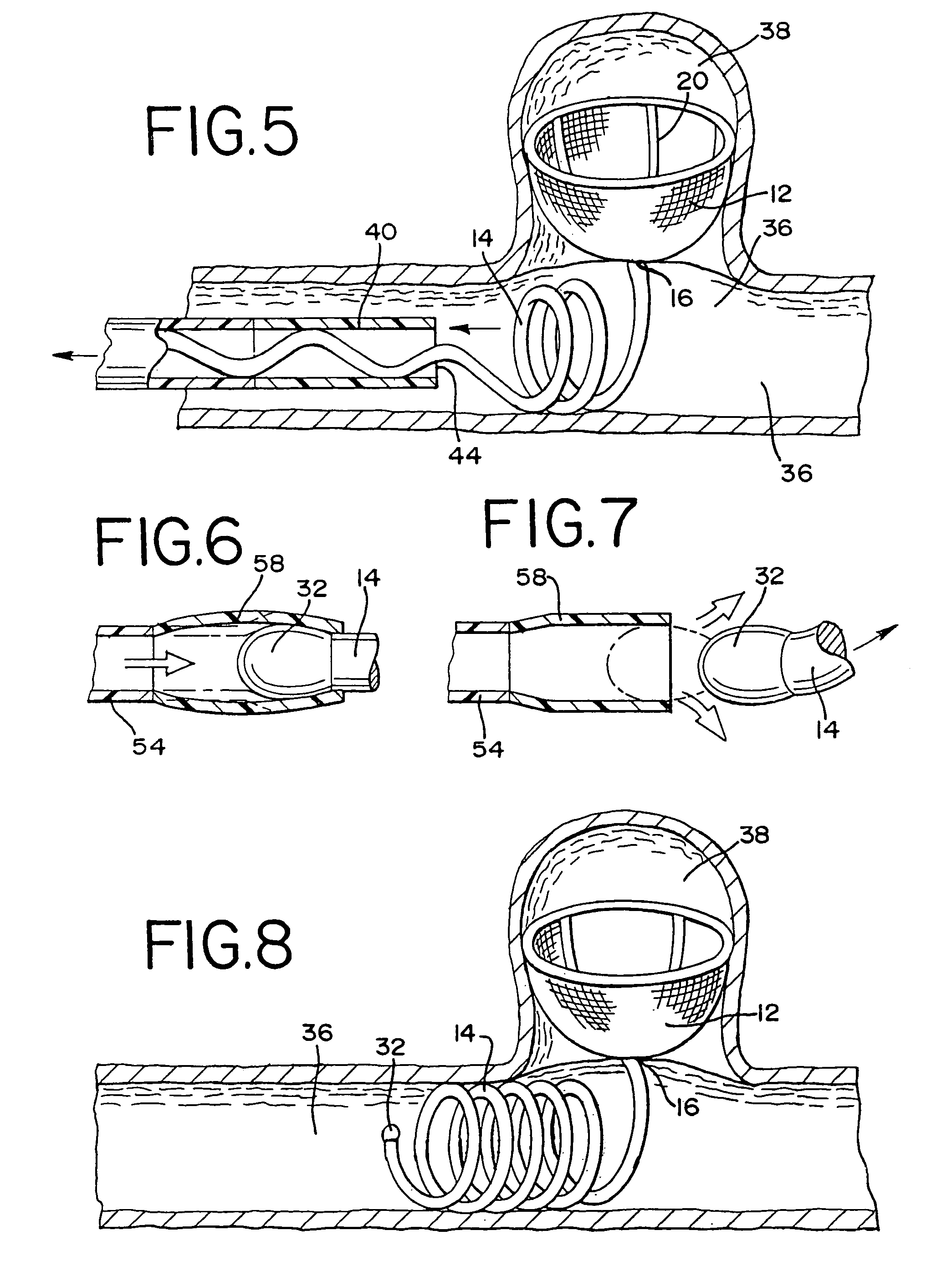
[0017]Referring to FIG. 1, a vaso-occlusive device 10 is illustrated therein including an embolization element 12 and a stent 14 connected at the base 16 of embolization element 12. The embolization element includes a collapsible framework in 18, 20, 22, 24 and 26, with an attached mesh or membrane 28 for reducing or blocking blood flow into an aneurysm or a vessel. Stent 14 is formed of a flexible wire that has been shaped into a cylindrical helix with its distal end 30 attached to the base 16 of embolization element 12.

[0018]In the illustrative embodiment, the stent 14 is formed of a superelastic material in wire or tube form that will form and retain the helical configuration of the stent. A platinum coil is placed over the core to provide radiopacity and aid in the delivery of the device. The core wire is enlarged at the proximal end 32 and the distal end 30, to fill the lumen of the coil. This provides a method of restricting the movement of the core wire relative to the platin...


PUM


Abstract

A method and device used for treating an aneurysm or a vessel of a patient. An embolization element that is adapted to reduce or block the blood flow into the aneurysm or vessel, together with a stent connected to the embolization element, is provided. The embolization element includes an expandible member. The embolization element and the stent are introduced into the vessel leading to and communicating with the aneurysm or vessel. The embolization element is directed into the aneurysm or vessel, with the stent being located in another vessel communicating with the first vessel. In this manner, the stent becomes compressed against the inner wall of the second vessel for anchoring the embolization element. In one form of the invention, the stent comprises a helical coil and the embolization element comprises a collapsible framework.

Description

CROSS-REFERENCE TO RELATED APPLICATIONS(S)[0001]This patent application is a continuation-in-part of U.S. patent application Ser. No. 09 / 957,183, filed on Sep. 20, 2001, now U.S. Pat. No. 6,811,560, entitled, “Stent Aneurysm Embolization Method And Device.”FIELD OF THE INVENTION[0002]The present invention concerns a novel device for treating a vessel of a patient and, more particularly, a device in which an embolic device is maintained within the vessel to prevent the flow of blood.BACKGROUND OF THE INVENTION[0003]A well-known method of treating an aneurysm of a vessel wall includes the placement of a number of embolic coils within the aneurysm. Typically, a deployment device is used to introduce the coils, one by one, via a microcatheter, into the aneurysm. In wider neck aneurysms, it has been found that the embolic coils tend to migrate back to the parent vessel, which may result in occlusion of the parent vessel. Further, migration of the coil or coils back into the parent vessel...

Claims


Application Information

Patent Timeline
Patent Type & Authority Patents(United States)
IPC IPC(8): A61F2/06A61B17/00A61B17/12A61F2/84
CPCA61B17/12022A61B17/12172A61B17/12118A61B2017/12081
Inventor JONES, DONALD K.MITELBERG, VLADIMIR
Owner CODMAN & SHURTLEFF INC
Why Eureka
Try Eureka