Magnetically actuated locking mechanism

a locking mechanism and magnet technology, applied in the direction of snap fasteners, buckles, applications for locking, etc., can solve the problems of difficult operation and complicated structure of locking devices, and achieve the effect of less diameter

Inactive Publication Date: 2007-12-18
WASHIN OPTICAL CO LTD
View PDF5 Cites 34 Cited by
  • Summary
  • Abstract
  • Description
  • Claims
  • Application Information

AI Technical Summary

Problems solved by technology

Generally, those known locking devices are complicated in structure and are difficult to operate.

Method used


Image

  • Magnetically actuated locking mechanism
  • Magnetically actuated locking mechanism
  • Magnetically actuated locking mechanism

Examples


Embodiment Construction

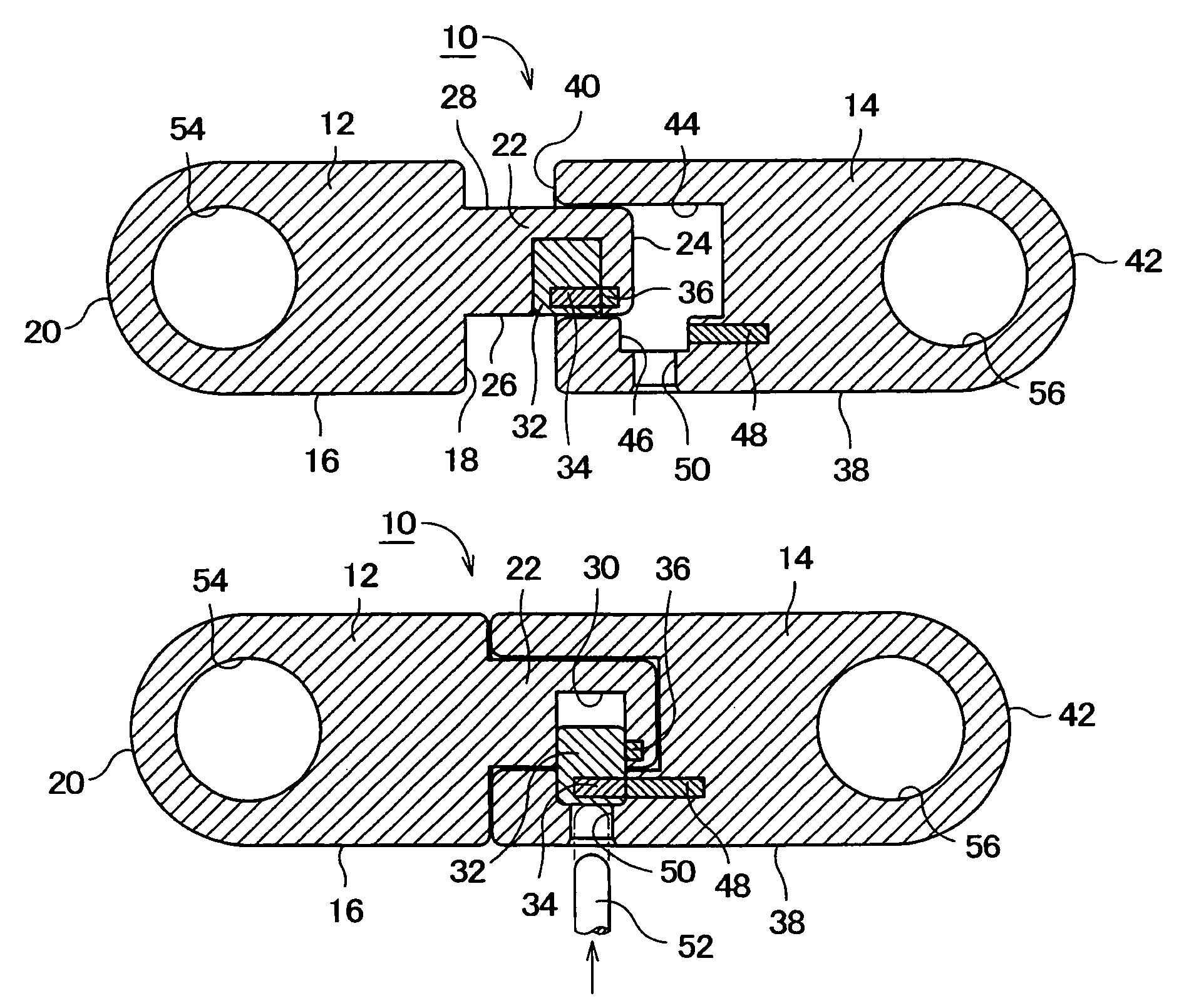
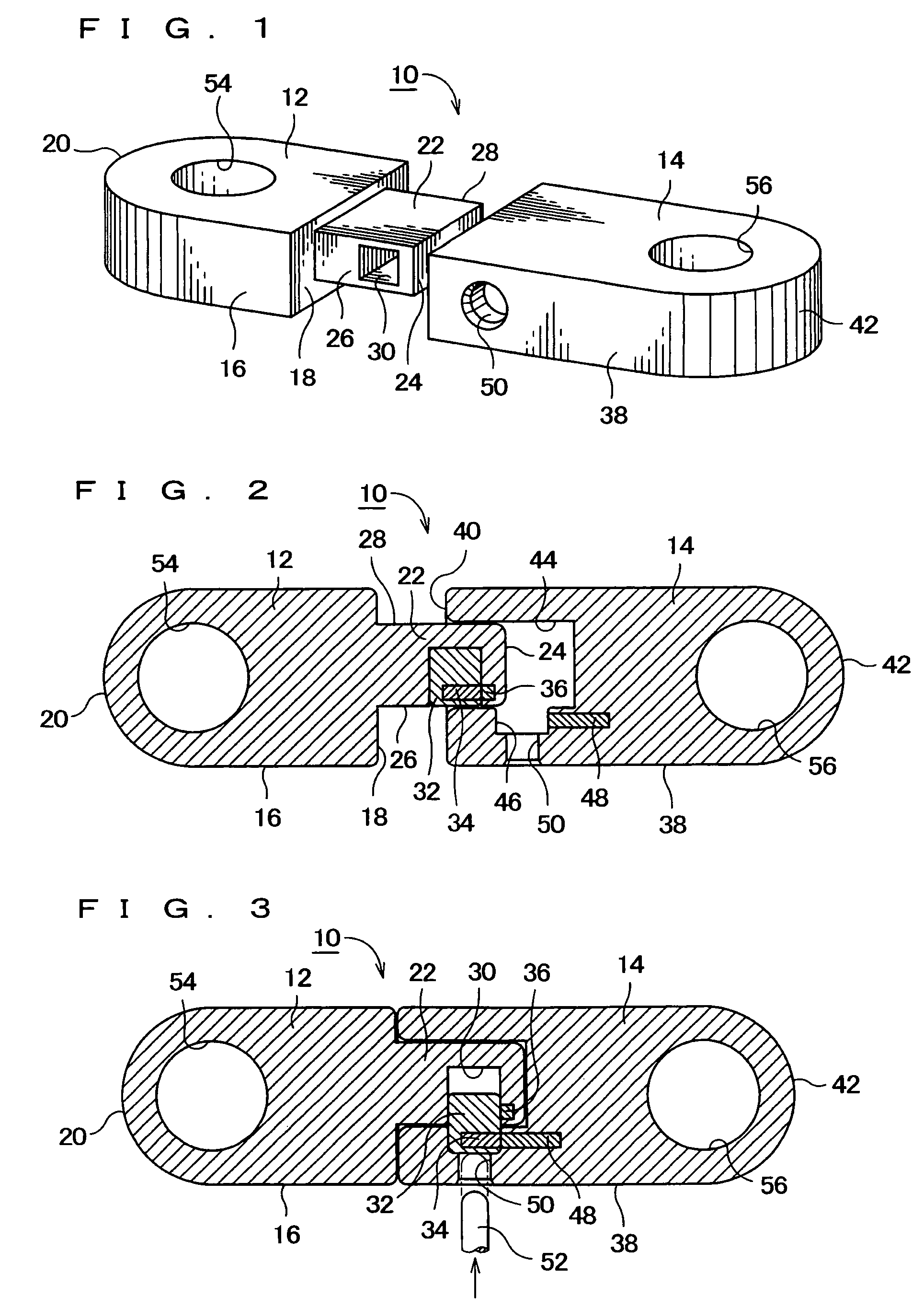
[0021]Referring now to FIGS. 1 to 3, there is illustrated a magnetically actuated locking mechanism, generally designated as at 10, according to one embodiment of the present invention. The locking mechanism 10 generally includes a male section 12 and a female section 14 releasably coupled to the male section 12.

[0022]The male section 12 includes a generally rectangular male body 16 with a flat end 18 and an opposite, round end 20. A rectangular projection 22 extends from the flat end 18 of the male body 16 and is less in width and thickness (or height) than the male body 16. The projection 22 has a free end 24. The projection 22 has opposite sides 26, 28 extending between the flat end 18 of the male body 16 and the free end 24 of the projection 22. A rectangular bore 30 is formed in the side 26 of the projection 22. The rectangular bore 30 extends in a direction substantially perpendicular to the direction in which the projection 22 extends. A rectangular locking element 32 (remove...


PUM


Abstract

A magnetically actuated locking mechanism includes a male section and a female section releasably coupled to the male section. The male section includes a male body, a projection extending from one end of the male body and including a transverse bore, and a locking element movable between an unlocked position wherein the locking element is received within the bore and a locked position wherein the locking element is partly extracted from the bore. A first magnet is embedded in the locking element. The female section includes a female body having a guide cavity dimensioned to receive the projection, and a transverse locking recess dimensioned to lockingly receive a part of the locking element as extracted. A second magnet is embedded in the female body adjacent to the locking recess. The first and second magnets have opposed polarities and are operatively associated with each other to magnetically urge the locking element from the unlocked position to the locked position when the locking element is aligned with the locking recess after the projection is inserted into the guide cavity.

Description

FIELD OF THE INVENTION[0001]The present invention generally relates to locking devices and more particularly, to a magnetically actuated locking mechanism wherein a plurality of magnetic elements are operatively associated with each other so as to magnetically urge the locking mechanism from an unlocked to locked position.BACKGROUND OF THE INVENTION[0002]A wide variety of locking devices are employed in a toy, a cabinet, a bag or briefcase, an ornament, a seat belt and etc. One example of such a known locking device uses a spring to urge a locking element from its unlocked to locked position. Another locking device includes a latch mechanism. Generally, those known locking devices are complicated in structure and are difficult to operate.[0003]It is, therefore, an object of the present invention to provide a magnetically actuated locking mechanism which is simple in structure and is easy to operate.SUMMARY OF THE INVENTION[0004]According to the present invention, there is provided a...

Claims


Application Information

Patent Timeline
Patent Type & Authority Patents(United States)
IPC IPC(8): A44B21/00A44B99/00
CPCE05B47/0038E05B67/003E05C19/163Y10T24/32E05C19/18E05B73/0005E03D9/08H04Q9/04
Inventor SAITOH, MASATOSHINEGISHI, TOHRU
Owner WASHIN OPTICAL CO LTD
Why Eureka
Try Eureka