Noise abatement wall

a technology of noise abatement and wall, which is applied in the direction of flooring, transportation and packaging, instruments, etc., can solve the problem that the solution of covering certain portions of roads or motorways is not always possibl

Inactive Publication Date: 2007-12-18
ECOLE POLYTECHNIQUE +1
View PDF29 Cites 30 Cited by
  • Summary
  • Abstract
  • Description
  • Claims
  • Application Information

AI Technical Summary

Problems solved by technology

The solution consisting in covering certain portio

Method used


Image

  • Noise abatement wall
  • Noise abatement wall
  • Noise abatement wall

Examples


Embodiment Construction

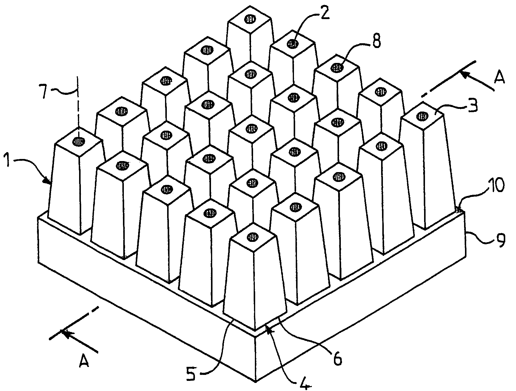
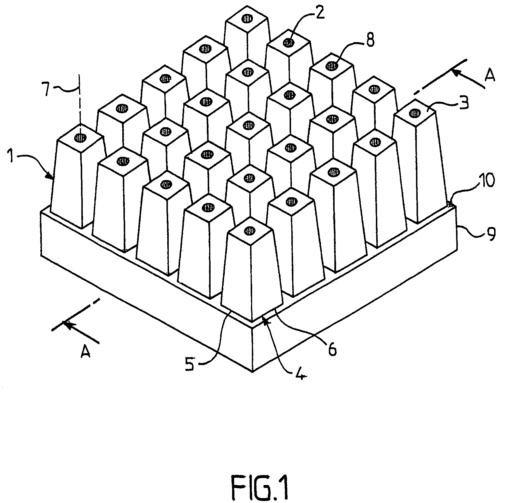
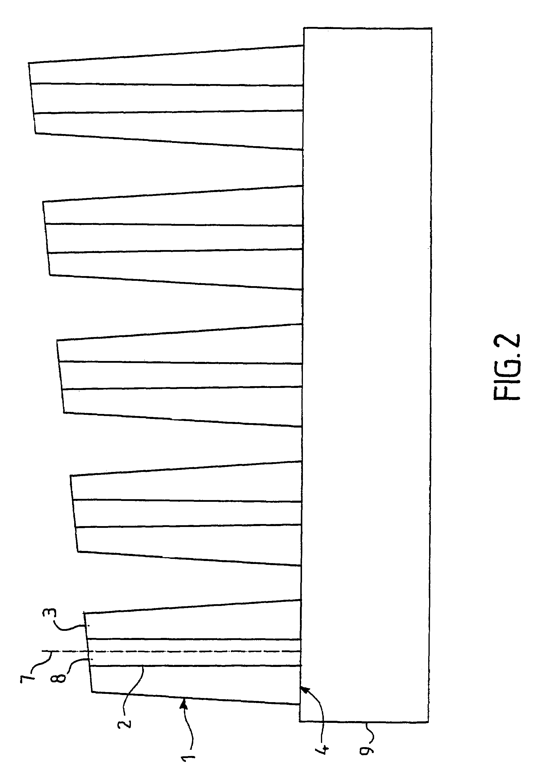
[0045]The sound-absorption device according to the invention implements the dampening design of fractal acoustic resonators. Here, the expression fractal object means an object whereof the geometry may be described by a non-integer dimension. This approach aims at realising a phonically absorbing object exhibiting maximal surface areas in a given volume, i.e. an object having a space filling surface. This is meant in the sense when the total surface area comprises in a sphere of radius R centred on the object varies more quickly when R increases than the square of the radius R. Such an object exhibits a very irregular geometry which enables the localisation of the modes of the waves over the sound frequency range, in the vicinity of the surfaces. The localisation of these modes for given frequencies, i.e. their concentration in a region of the space close to the phonically absorbing surfaces causes excessive dampening effect of these modes. This excessive dampening effect results fr...


PUM


Abstract

A noise-absorbing device includes a substantially flat base and embossed and/or hollow elements each including at least one recess. This base reveals with the embossed and/or hollow elements, a configuration exhibiting a fractality zone of between 1 cm and 50 cm, of fractal dimension greater than 2.5 enabling the localization of the waves over the sound frequency range, in the vicinity of the elements.

Description

BACKGROUND OF THE INVENTION[0001]The present invention relates to a soundproof wall. It aims at limiting the effects of the noise, among other things noises issued from various modes of transportation (roads, railways, airports). This soundproof device may be arranged on any type of infrastructure (wall, ceiling, floor, tunnel, building, . . . ).[0002]The solution consisting in covering certain portions of roads or of motorways is not always possible. Often, it is sought to attenuate, if not to suppress, the effects of the noise by the construction on the bank of the carriageway, soundproof walls, also called acoustic screens, along the existing carriageways.[0003]The conception of these soundproof walls results from the application of the circular R / A 89.66 dated 17 May 1989 which defines the requirements thereof in terms of noise, aesthetics and cost.[0004]Generally, it is known that the sizing method of such walls is based on the calculation of the direct transmissions and on the...

Claims


Application Information

Patent Timeline
IPC IPC(8): G10K11/16E04B1/82E04B1/84E04H17/14E01F8/00E04B1/86
CPCE01F8/0029E01F8/0076E04B1/86E04B2001/8419E04B2001/8414
Inventor SAPOVAL, BERNARDFILOCHE, MARCELCHAPPAT, MICHELPEYRARD, DIDIER
Owner ECOLE POLYTECHNIQUE
Why Eureka
Try Eureka