Cable protection system

a protection system and cable protector technology, applied in the direction of cables, insulated conductors, ways, etc., can solve the problems of inefficient waste, affecting the overall width of the cable protector, and affecting the safety of the elderly or handicapped

Active Publication Date: 2007-12-18
CHECKERS INDAL PRODS
View PDF42 Cites 71 Cited by
  • Summary
  • Abstract
  • Description
  • Claims
  • Application Information

AI Technical Summary

Benefits of technology

[0014]According to some embodiments, a cable protection system comprises at least one cable protector having a base member, at least one channel extending between opposing ends of the base member and structured to receive at least one cable, at least one vertically oriented slot defined in a first side of the base member, a coupling recess defined within the slot in the base member, a first ramp comprising at least one vertically oriented connector, and a coupling structure formed on the connector of the first ramp. The coupling structure formed on the connector of the first ramp may be configured to removably snap fit into the coupling recess defined within the slot in the base member to removably attach the first ramp to the first side of the base member.

Problems solved by technology

Although this relatively steep slope is easily navigable by motorized vehicles and pedestrians of average strength, these slopes can be a significant hurdle or obstacle to the elderly or handicapped.
The connectors used to detachably interlock or connect the various modular elements in conventional modular cable protection systems, whether or not the ramps of the system have been adapted for use by the handicapped and elderly, suffer from a number of drawbacks and disadvantages.
For example, the complimentary male and female T-shaped connectors formed along the sides of the main cable protector undesirably increase the overall width of the cable protector without increasing the cable-housing capacity of the cable protector itself.
This configuration results in an inefficient waste in the amount of material required to produce the cable protector, which in turn results in an undesirable increase in overall production costs.
Specifically, because the protrusions formed on these strap-like ramp connectors must be engaged within recesses formed on the undersides of the wheelchair ramps and the cable protector, a user attempting to interconnect these elements may struggle to correctly align the protrusions within the appropriate recess when the undersides of the cable protector and the ramps are positioned so as to face the ground.
In addition, because the detachable connection formed by engaging the strap-like connector's protrusions in the appropriate recesses is relatively weak, a strong torsional force applied to the wheelchair ramp (such as one transferred from the wheel of a heavy or powered vehicle) may be large enough to pull or break the protrusion from the recess it is engaged within.

Method used


Image

  • Cable protection system
  • Cable protection system
  • Cable protection system

Examples


Embodiment Construction

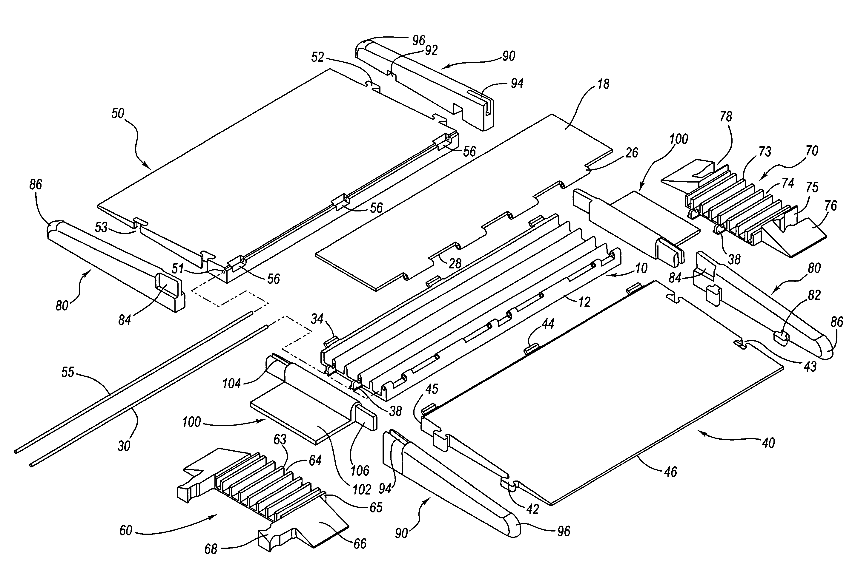
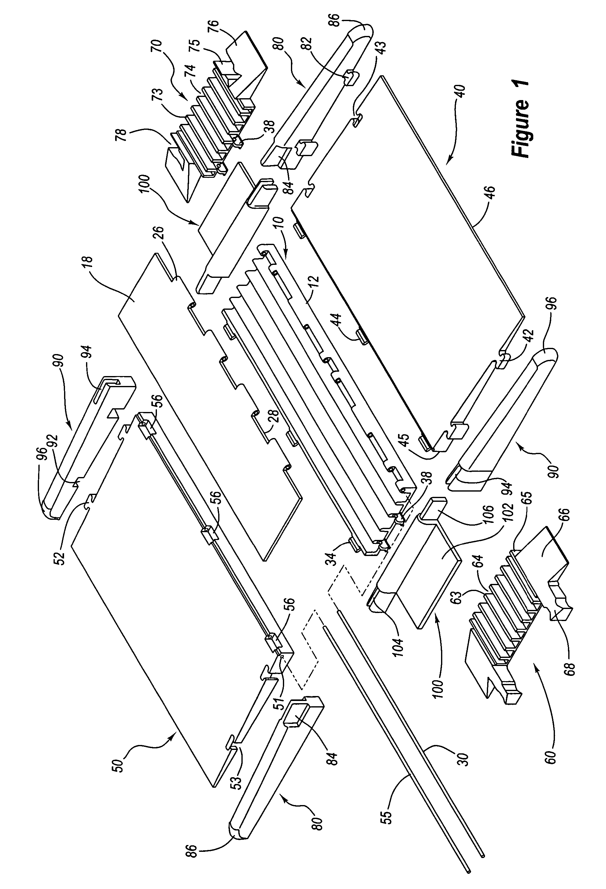
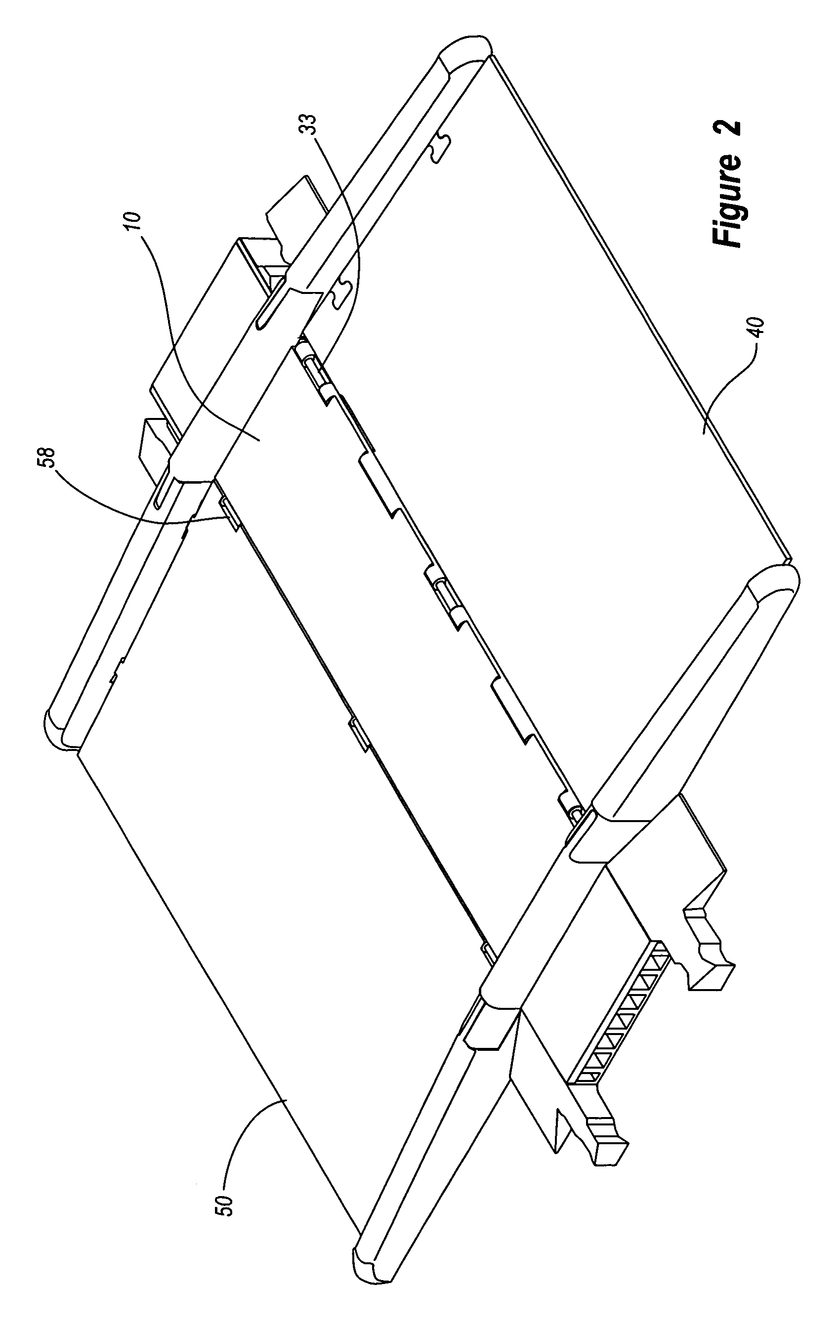
[0039]FIG. 1 is an exploded top view of an exemplary cable protection system according to at least one embodiment. FIG. 2 is an assembled top view of the exemplary cable protection system illustrated in FIG. 1. In one embodiment, the exemplary cable protection system illustrated in these figures comprises a pair of ramps 40, 50 that are removably and pivotally attachable to a cable protector 10.

[0040]As seen in FIGS. 1 and 3, in certain embodiments cable protector 10 comprises a base member 12 having a pair of opposing side walls 13. Base member 12 may be substantially rectangular, as illustrated in FIGS. 1-3, or formed in any number of other shapes or sizes, such as a square or other multi-sided shape. As seen in the end view of FIG. 4A, in one embodiment opposing side walls 13 are substantially vertically extending.

[0041]In certain embodiments, opposing side walls 13 form a single channel within base member 12 for housing one or more cables. Alternatively, as illustrated in FIG. 3...


PUM


Abstract

A cable protection system includes at least one cable protector having at least one channel extending between its opposing ends for receiving at least one cable. The cable protector may include a cover structure pivotally attached to a base member by a hinge rod inserted through hinge members formed in the cover structure and the base member. A first ramp or an additional cable protector may be attached to the cable protector by inserting one or more connectors formed on the first ramp or additional cable protector into vertically oriented apertures defined in a side of the cable protector. One or more connectors may also be formed on a side of the cable protector opposing the apertures to removably attach the cable protector to a second ramp or an additional cable protector.

Description

FIELD OF THE INVENTION[0001]The present invention relates generally to cable protectors and cable protection systems.BACKGROUND OF THE INVENTION[0002]Over the years, various devices and apparatuses have been developed in an effort to protect hoses, cables, wiring and the like from physical damage. In particular, numerous cable protector designs have been developed to protect cabling extending across walkways, roadways, and construction sites from physical damage caused by pedestrians, vehicular traffic and other such external elements. Cable protectors have also proven useful in helping to minimize the risk of pedestrians tripping over such cabling. For the purposes of this disclosure, the terms “cable” and “cabling” shall be broadly construed to include data cables, hoses, electrical wiring, telephone cables, conduits, optical fibers, pneumatic tubing, plumbing, and any other length of material.[0003]Conventional cable protectors typically include one or more channels extending in ...

Claims


Application Information

Patent Timeline
Patent Type & Authority Patents(United States)
IPC IPC(8): H02G3/30E01B7/28
CPCH02G3/0418H02G3/0487H02G9/02H02G9/04H02G3/34Y10T403/7117
Inventor LUBANSKI, THOMAS M.
Owner CHECKERS INDAL PRODS
Why Eureka
Try Eureka