Rolling mechanism for window blind

a technology for window blinds and rolling mechanisms, which is applied in the direction of shutters/movable grilles, door/window protective devices, wing arrangements, etc., can solve the problems of ineffective blinding of windows, and achieve the effect of improving the rolling mechanism and improving the rolling mechanism of windows

Inactive Publication Date: 2007-12-25
NIEN MADE ENTERPRISE CO LTD
View PDF10 Cites 59 Cited by
  • Summary
  • Abstract
  • Description
  • Claims
  • Application Information

AI Technical Summary

Problems solved by technology

According to the aforesaid design, the roller fails be firmly positioned after the shade fully released, thereby ineffectively blinding the window.

Method used


Image

  • Rolling mechanism for window blind
  • Rolling mechanism for window blind
  • Rolling mechanism for window blind

Examples


Embodiment Construction

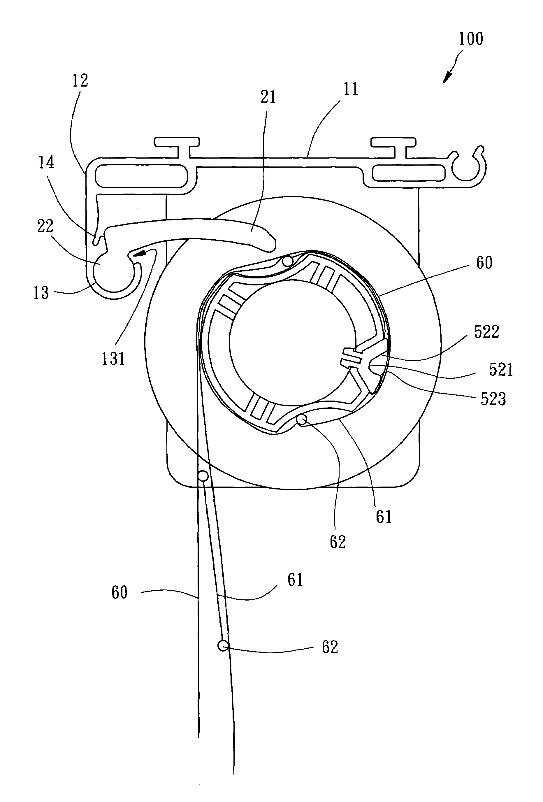
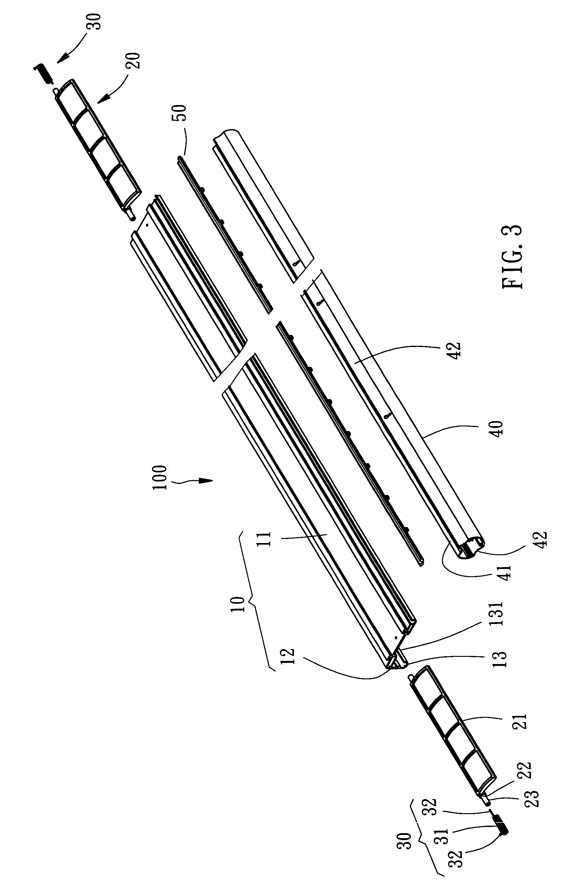
[0017]Referring to FIGS. 3-5, a rolling mechanism 100 for a window blind in accordance with a first preferred embodiment of the present invention is shown comprised of a base frame 10, at least one constraint member (two constraint members) 20, at least one springy member (four springy members) 30, a roller 40, and a locating member 50.

[0018]The base frame 10 is shaped like a L-shaped elongated bar and fastened to a top side of a window, including an elongated first frame panel 11 and an elongated second frame panel 12 arranged at a right angle. The second frame panel 12 extends outwards from the first frame panel 11, having a coupling flange 13 of circular cross-section, an elongated opening 131 formed over the coupling flange 13, and a longitudinal retaining groove 14 formed on an inner wall of the coupling flange 13 (see FIG. 6).

[0019]The constraint members 20 are identical to each other and respectively coupled to two distal ends of the coupling flange 13 of the base frame 10 an...


PUM


Abstract

A rolling mechanism includes a base frame fastened to a top side of a window and having a coupling flange, a roller rotatably mounted below the base frame for stationary rotation and having a locating groove on its periphery, and at least one constraint member having a coupling portion pivotally coupled to the coupling flange of the base frame and a constraint portion extending from the coupling portion for engaging the locating groove of the roller and further limiting the rotary direction of the roller to one direction only.

Description

[0001]This Non-provisional application claims priority under 35 U.S.C. 119(a) on Patent Application No(s). 093207261 filed in Taiwan, Republic of China on May 10, 2004, the entire contents of which are hereby incorporated by reference.BACKGROUND OF THE INVENTION[0002]1. Field of the Invention[0003]The present invention relates to window blinds, and more specifically to a rolling mechanism for preventing roller of a window blind from reverse rolling.[0004]2. Description of the Related Art[0005]A conventional window blind, such as a roller-typed shade, as shown in FIGS. 1 and 2, essentially is comprised of a roller 1 and a shade 2. The roller 1 is rotatably mounted at a top side of a window for stationary rotation driven by an external force generally generated from a rolling mechanism having an endless lifting cord or chain and connected with the roller 1. The shade 2 has an end fastened to an outer periphery of the roller 1 and a free end suspended from the roller 1 for blinding the...

Claims


Application Information

Patent Timeline
Patent Type & Authority Patents(United States)
IPC IPC(8): E06B9/08A47H5/00E06B3/48E06B9/34E06B9/44E06B9/48
CPCE06B9/34E06B9/48E06B2009/2435
Inventor NIEN, MINGWEN, YUCHECHANG, CHIH-YAO
Owner NIEN MADE ENTERPRISE CO LTD
Why Eureka
Try Eureka