Two-cone drill bit with enhanced stability

a drill bit and stability technology, applied in drill bits, earthwork drilling and mining, cutting machines, etc., can solve problems such as extensive damage to drill bit tools

Inactive Publication Date: 2008-01-08
SMITH INT INC
View PDF27 Cites 6 Cited by
  • Summary
  • Abstract
  • Description
  • Claims
  • Application Information

AI Technical Summary

Problems solved by technology

Two-cone drill bits greatly improved drilling rates in the early 1900's, but were found to suffer severe near bit vibrations, which resulted in extensive damage to downhole tools.

Method used


Image

  • Two-cone drill bit with enhanced stability
  • Two-cone drill bit with enhanced stability
  • Two-cone drill bit with enhanced stability

Examples


Embodiment Construction

[0013]In one or more embodiments, the present invention relates to two-cone drill bits. More specifically, the present invention relates to two-cone drill bits having improved stability.

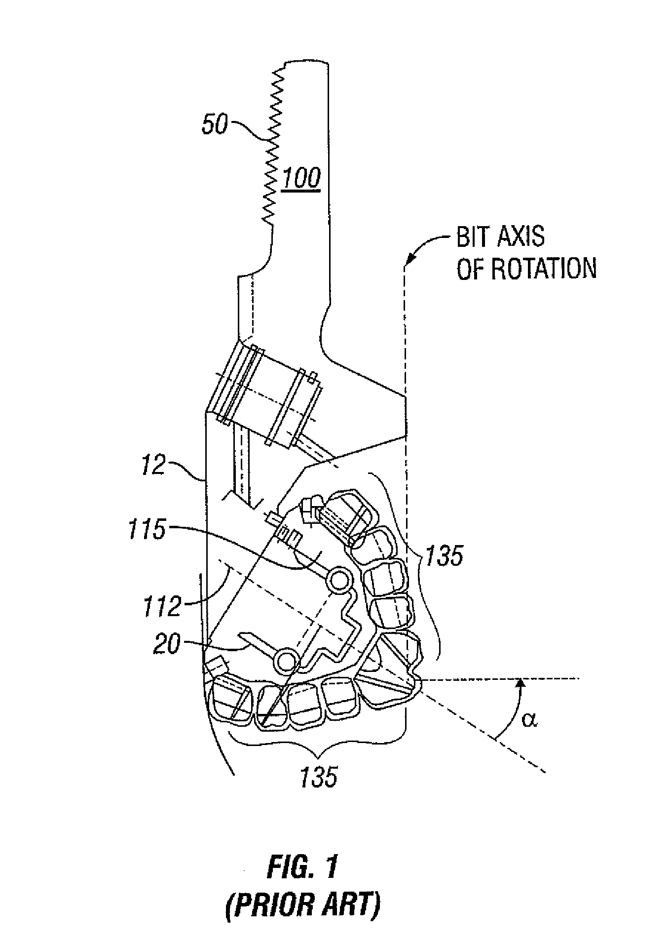
[0014]In FIG. 1, a cross section of a prior art three-cone drill bit is shown. The portion of the drill bit that is shown includes a bit body 100 and a roller cone 115 having a plurality of cutting elements 135. A connection 50 is formed on the upper end of the bit body 100 for connection to a drill string (not shown). The roller cone 115 is rotatably mounted on a journal 20, which is disposed on a leg 12 formed on the bit body 100. During drilling, the roller cone 115 rotates about the journal axis 112. The journal axis 112 is oriented at a journal angle α, which is typically measured relative to a horizontal line that is drawn perpendicular to the bit axis of rotation.

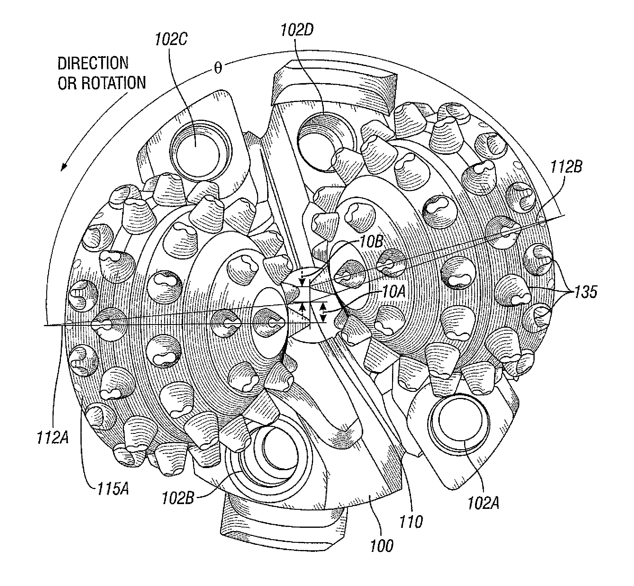
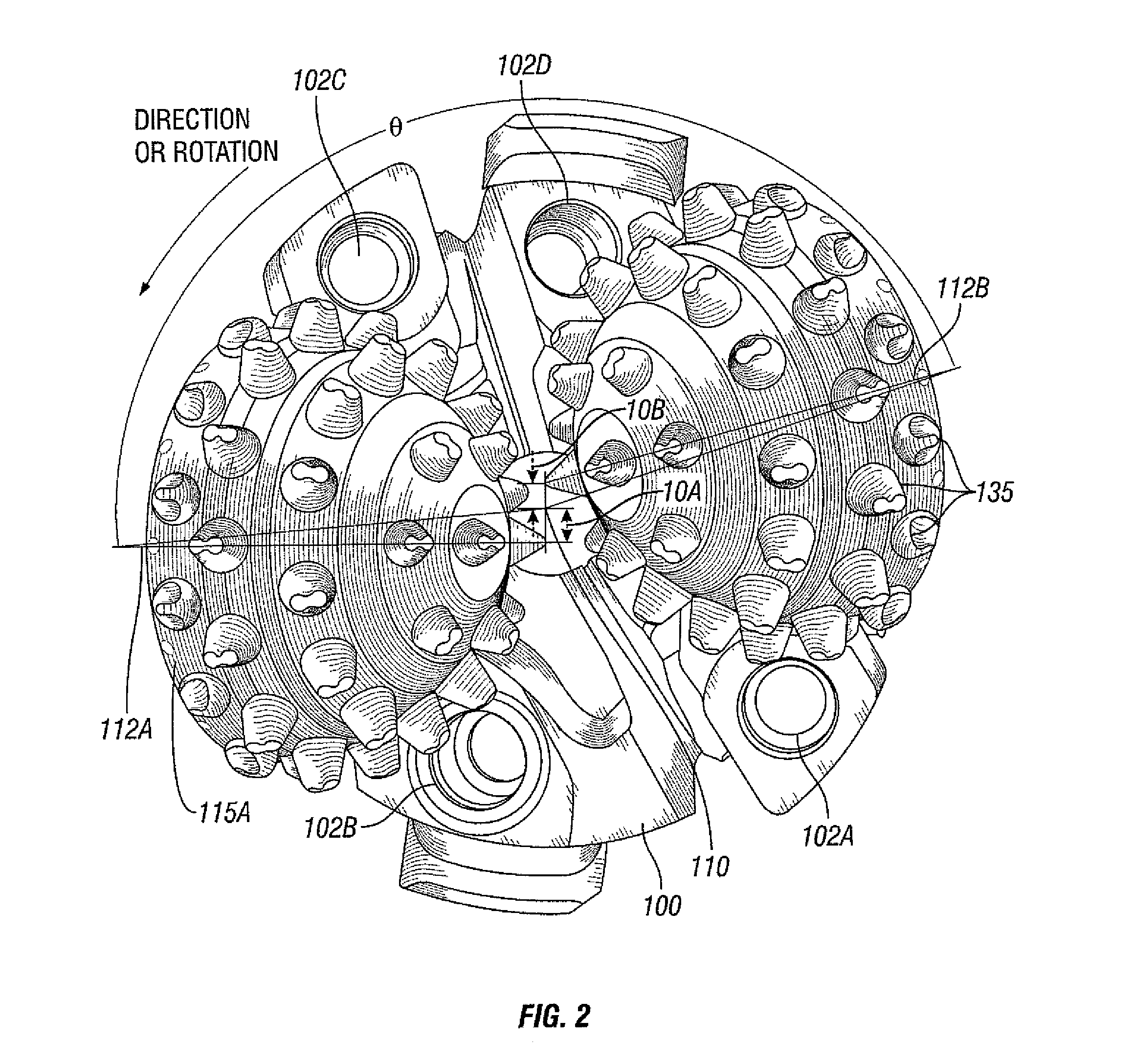
[0015]In FIG. 2, a two-cone drill bit in accordance with one embodiment of the present invention is shown. In this embodiment, two r...


PUM


Abstract

A two-cone drill bit that exhibits improved stability. In one embodiment, the two-cone drill bit has a first and a second roller cone arranged to have a cone separation angle between about 145 degrees and about 166 degrees. In some embodiments, the two-cone drill bit has a plurality of cutting elements arranged on the roller cones such that a bottom hole coverage greater than about 17 percent is achieved per revolution of the two-cone drill bit.

Description

BACKGROUND OF INVENTION[0001]Roller cone bits, variously referred to as rock bits or drill bits, are used in earth drilling applications. Typically, they are used in petroleum or mining operations where the cost of drilling is significantly affected by the rate that the drill bits penetrate the various types of subterranean formations. That rate is referred to as rate of penetration (“ROP”), and is typically measured in feet per hour. There is a continual effort to optimize the design of drill bits to more rapidly drill specific formations so as to reduce these drilling costs.[0002]Roller cone bits are characterized by having roller cones rotatably mounted on legs of a bit body. Each roller cone has an arrangement of cutting elements attached to or formed integrally with the roller cone. A roller cone bit having two cones was invented in 1908 and is the predecessor of the more common three-cone bit. Two-cone drill bits greatly improved drilling rates in the early 1900's, but were fo...

Claims


Application Information

Patent Timeline
Patent Type & Authority Patents(United States)
IPC IPC(8): E21B10/36E21B10/08E21B10/16
CPCE21B10/08E21B10/086E21B10/16E21B10/18
Inventor BOUDRARE, MOHAMMEDCENTALA, PRABHAKARAN K.
Owner SMITH INT INC
Why Eureka
Try Eureka