Mass spectrometer and mass analysis method

a mass spectrometer and mass analysis technology, applied in the field of mass spectrometers, can solve the problems of reducing the usability of ions, affecting the separation effect of ions, so as to achieve effective separation of ions. the effect of high sensitivity

Active Publication Date: 2008-01-15
HITACHI HIGH-TECH CORP
View PDF5 Cites 8 Cited by
  • Summary
  • Abstract
  • Description
  • Claims
  • Application Information

AI Technical Summary

Benefits of technology

[0012]It is an object of the invention to provide a method of high-speed charge separation using a linear trap. As can be seen from the above-mentioned formula (1), the shorter the charge separation time is, the higher the duty cycle of ions, and thus the sensitivity is improved.
[0013]It is another object of the invention to provide a mass spectrometer with a simple structure and high sensitivity. It should be noted that in the method as disclosed in the U.S. Pat. No. 5,905,258, a system for speedy data processing is needed, resulting in high costs, and ions diffuse during mobility separation of several tens ms, resulting in significantly decreased sensitivity.
[0018]The invention can provide apparatus and method for analyzing ions with high sensitivity in a speedy manner using a linear trap for selectively allowing passage of multiple charge ions. Further, the invention can provide apparatus and method for enabling effective separation of ion mobility.

Problems solved by technology

The challenge to charge separation by means of hardware is to achieve speed-up.
In a linear trap, during the charge separation, other measurement sequences are suspended, disadvantageously leading to a decrease in usability of ions, namely, sensitivity in the whole device.
However, as the potential on the axis is decreased, the charge selectivity or separation is also degraded due to an influence from a fringing field.
That is, in the technology as disclosed in the U.S. Pat. No. 2002 / 0175279, the selectivity and sensitivity of ions are not compatible with each other.
Such loss of duty cycle leads to significant decrease in sensitivity of the whole device.

Method used


Image

  • Mass spectrometer and mass analysis method
  • Mass spectrometer and mass analysis method
  • Mass spectrometer and mass analysis method

Examples


first embodiment

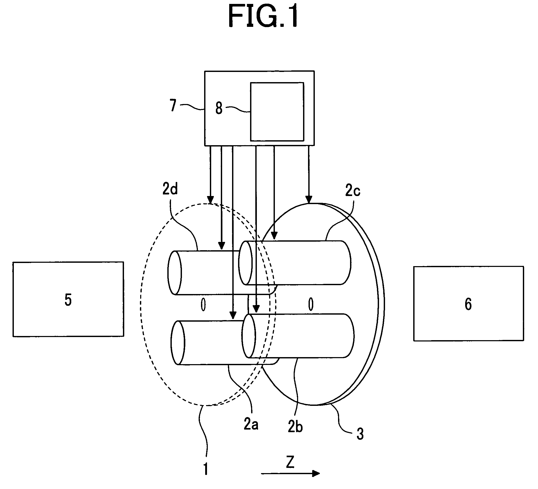
[0030]FIG. 1 is a diagram of a configuration of a mass spectrometer using a linear trap section enabling charge separation according to a first preferred embodiment of the invention. Ions are generated by an ion source 5, such as an electrospray ion source, or a Matrix Assisted Lasor Desorption Ionization ion source. The ions generated are introduced via a differential pumping region, and an ion guide, which are not shown, into a linear trap comprising four rods 2, and end lenses 1 and 3 on both sides thereof. Application of a voltage to the linear trap is performed by a power supply 7 for a controller. Typically, the length of the rod 2 is set to 7.0 mm, the diameter of a pole to 7.0 mm, a distance between the poles to 7.0 mm, and a distance between the rod 2 and the end lenses 1, 3 to about 10 mm. Trap RF voltages (frequency: 500 to 3 MHz (typically, 1 MHz), and amplitude: 100 V to 5 kV) are applied to the rods 2 such that the adjacent rods are subjected to the voltages in opposit...

second embodiment

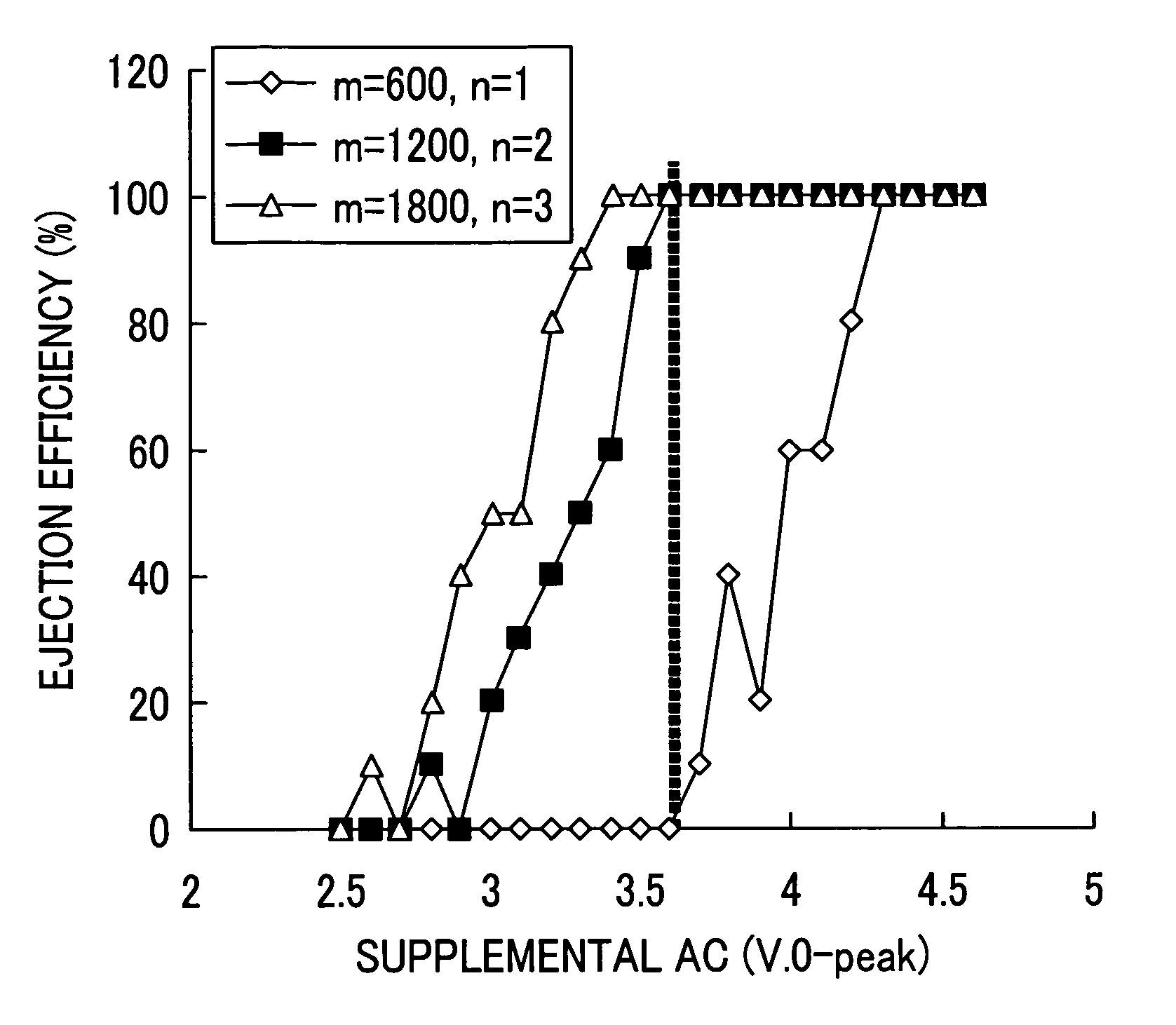
[0045]In the above-mentioned embodiment, charge separation of ions with the specific range of mass-to-charge ratios is performed using the supplemental AC voltage with a single frequency. In a second preferred embodiment, charge separation of ions with a wide range of mass-to-charge ratios is also allowed. A composite wave with a frequency fN represented by the following formula (8) (typically 1 to 50 kHz, changed by 0.5 kHz) is used as a supplemental AC voltage.

[0046]∑N⁢AN⁢sin⁡(2⁢π⁢⁢fN⁢t+ϕN)

In this case, since an appropriate voltage is different depending on the mass-to-charge ratio (frequency), it is necessary to give a voltage gain AN which differs depending on each frequency component fN. Ions resonate with only the frequency component in the vicinity of the resonance frequency to be ejected into the mass spectrometry section 6. Also in this case, a frequency and a voltage gain AN of a supplemental AC voltage for ejecting only ions with high charge and retaining ions with low ch...

third embodiment

[0047]In the third embodiment, the charge separation trap described in the first embodiment is applied particularly to an ion source and an intermediate section (differential pumping region) of a mass spectrometry section. This application is illustrated in FIG. 6. Ions are generated by an atmospheric pressure ion source 101, such as an electrospray ion source, an atmospheric pressure chemical ion source, an atmospheric pressure light ion source, or an atmospheric pressure matrix assisted laser desorption ion source. The ions generated are introduced into a first differential pumping region 103 via a first porous lens 102. The first differential pumping region is exhausted by a vacuum pump (not shown), and is maintained at 1 to 10 Torr (130 to 1300 Pa, the main component being air) The ions pass through a second porous lens 104 to be introduced into a second differential pumping region 105 where the trap of the invention is disposed. In the second differential pumping region 105, a ...


PUM

PropertyMeasurementUnit
pressureaaaaaaaaaa
pressureaaaaaaaaaa
ejection timeaaaaaaaaaa

Abstract

A linear trap which allows for charge separation and ion mobility separation in a speedy manner, and enables measurement with high duty cycle. A mass spectrometer comprises an ion source, an ion trap for trapping ions ionized by the ion source, an ion trap controller for controlling a voltage on an electrode included in the ion trap, and a detector for detecting the ions ejected from the ion trap. The ion trap controller includes a table for each mass-to-charge ratio, the table containing a frequency of the voltage used for charge separation, and a gain of the voltage for ejecting a first ion with a first charge outside the ion trap, and retaining in the ion trap a second group of ions with a second charge that is lower than that of the first charge. The ion trap controller controls the voltage based on the mass-to-charge ratio set. The mass spectrometer has significantly improved sensitivity, as compared to the prior art.

Description

CLAIM OF PRIORITY[0001]The present application claims priority from Japanese applications JP 2005-078367 filed on Mar. 18, 2005, and JP 2005-222327 filed on Aug. 1, 2005, the contents of which are hereby incorporated by reference into this application.FIELD OF THE INVENTION[0002]The present invention relates to mass spectrometers.BACKGROUND OF THE INVENTION[0003]In mass spectrometers used for proteome analysis or the like, separation of multiple charge ions is very important. In electrospray ionization, most of noise ions are singly charged, whereas peptide ions tend to be multiply charged. Accordingly, technologies are very important for effective separation of only multiple charge ions from singly charged ions. Information on the charge number is obtained by analyzing mass spectra provided as a result of measurements with high resolution and less spectrum duplication. A sample previously subjected to a simple pretreatment, however, contains multiple components, and spectra thereof...

Claims


Application Information

Patent Timeline
Patent Type & Authority Patents(United States)
IPC IPC(8): H01J49/00
CPCH01J49/0027H01J49/4225
Inventor HASHIMOTO, YUICHIROHASEGAWA, HIDEKIWAKI, IZUMI
Owner HITACHI HIGH-TECH CORP
Why Eureka
Try Eureka