Robotic extraction cleaner with dusting pad

a robot and dusting pad technology, applied in the field of robot extraction cleaners, can solve the problems of reducing the useful life of cloths, reducing the capacity of cleaning types to pretreat and agitate stubborn sticky stains, and pushed debris in front of the robot without being picked up

Active Publication Date: 2008-01-22
BISSELL INC
View PDF21 Cites 299 Cited by
  • Summary
  • Abstract
  • Description
  • Claims
  • Application Information

AI Technical Summary

Benefits of technology

[0007]Preferably, the cleaning robot further includes floor condition sensors mounted on the base housing for detecting a floor condition and for generating a control signal that forms a part of the input data to the computer processing unit. Further, the computer processing unit controls at least one of the agitator, the delivery of fluid by the fluid delivery system, the suction source and the drive system in response to the control signal. In a preferred embodiment, proximity sensors are mounted on base housing for detecting the

Problems solved by technology

One limitation of these types of robot cleaners is that larger debris is pushed in front of the robot without being picked up.
Another limitation is that the larger debris tends to clog or bind the cloth, thus reducing the useful life of the cloth.
A further limitation is that this type o

Method used


Image

  • Robotic extraction cleaner with dusting pad
  • Robotic extraction cleaner with dusting pad
  • Robotic extraction cleaner with dusting pad

Examples


Embodiment Construction

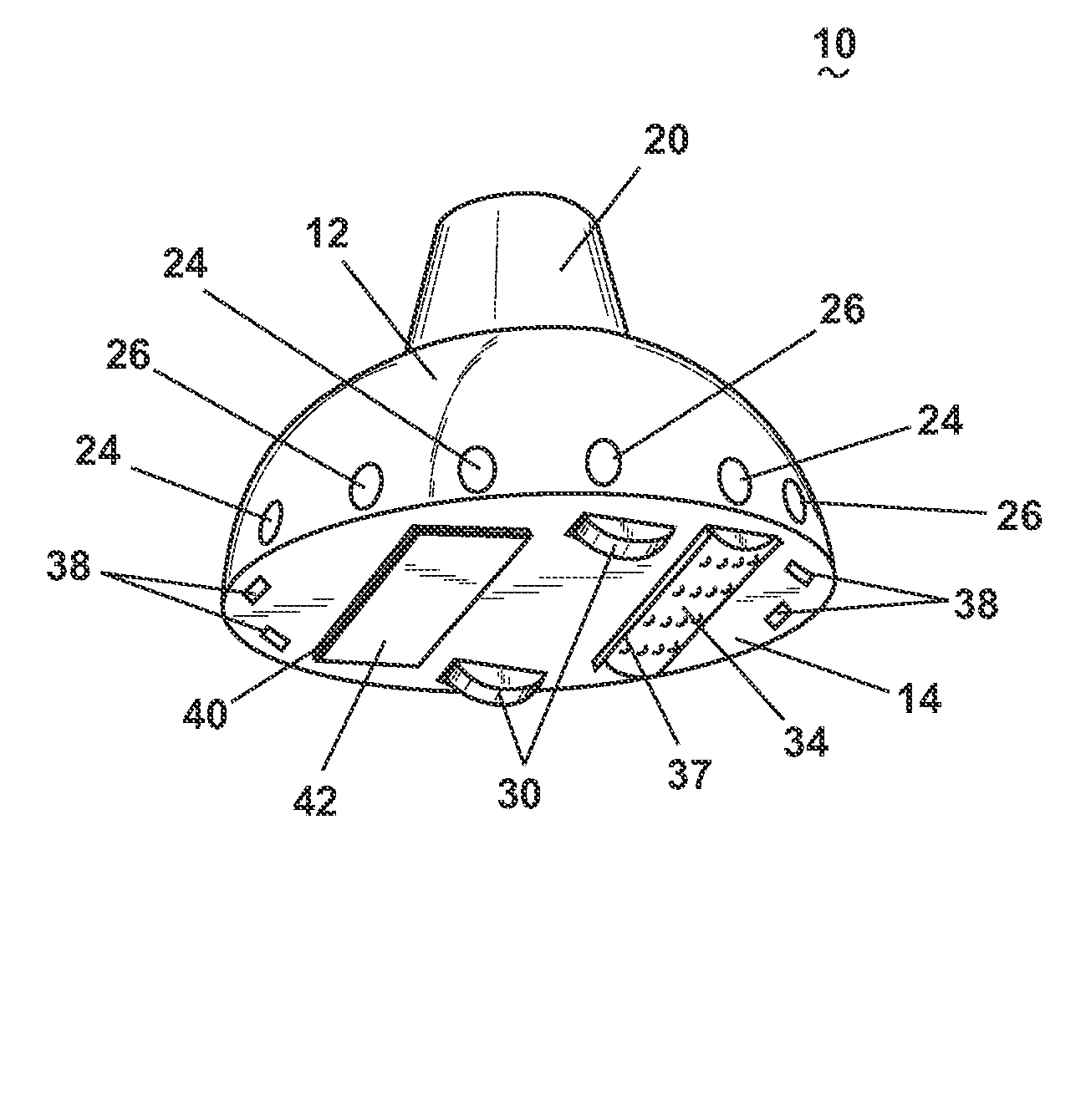
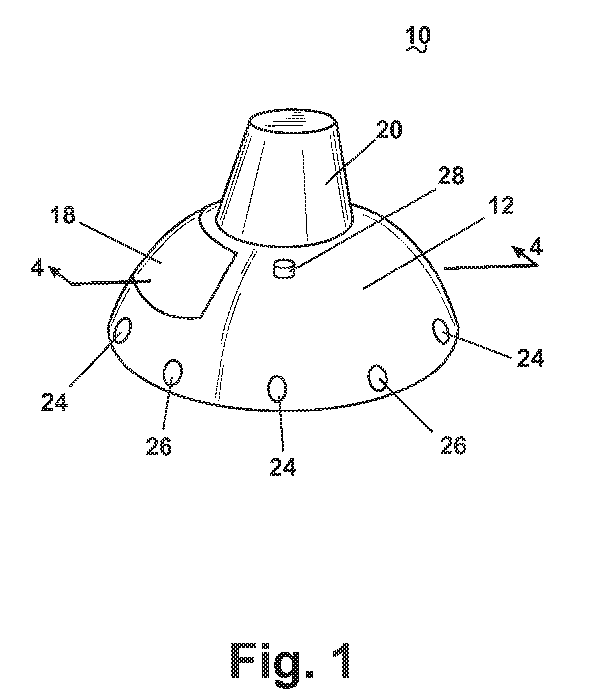
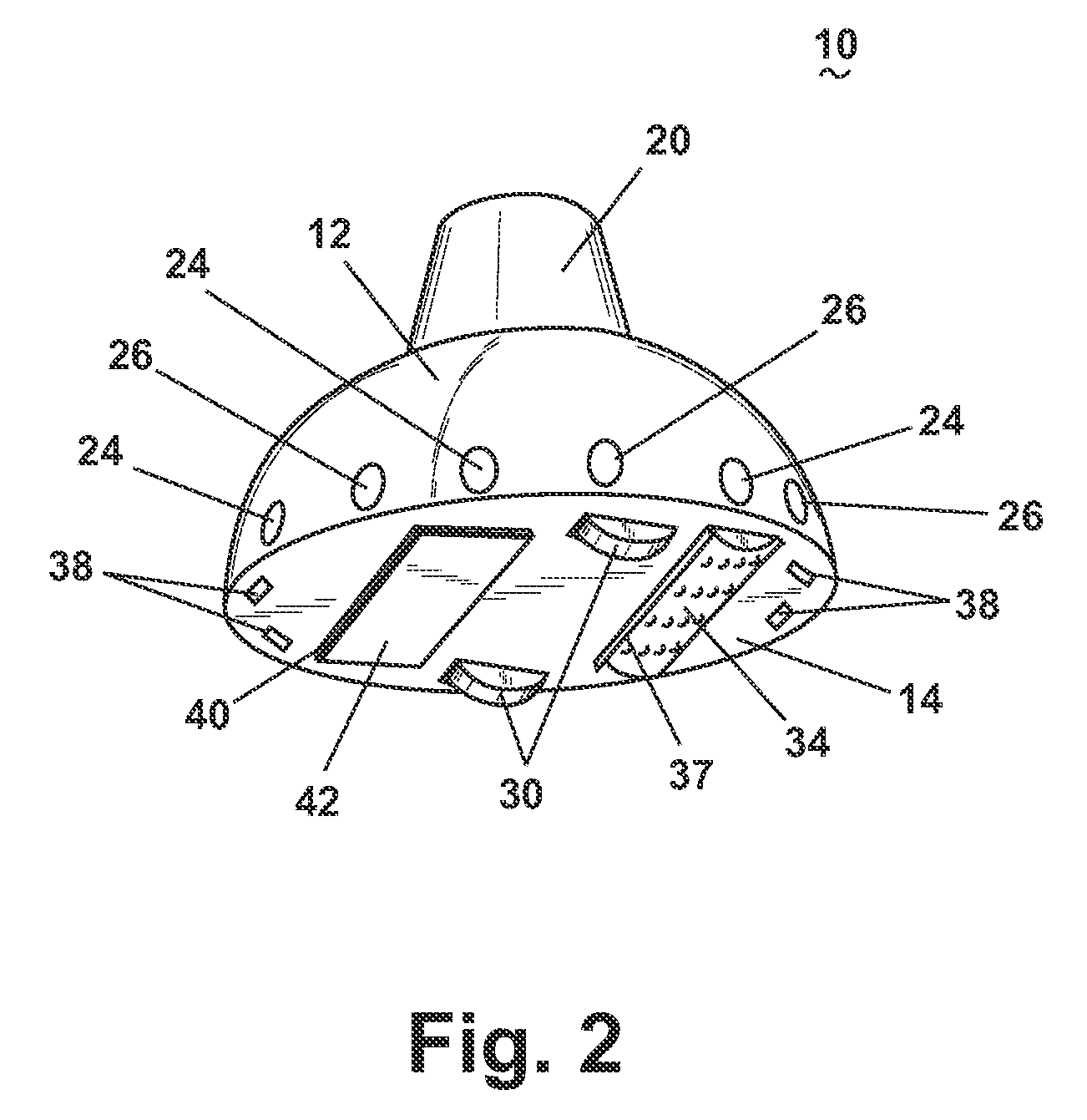
[0021]Referring to FIGS. 1-3, a robotic extraction cleaner 10 with dusting pad is described and comprises robotic platform further comprising a top enclosure 12 and a base housing 14. The base housing 14 provides the basic structure for the robotic platform on which all other components depend for structural support. A clean solution tank 16 is removably mounted in a solution tank recess 18 formed within the top enclosure 12. A generally conical shaped recovery tank 20 is removably mounted to a flat surface formed on a top surface of top enclosure 12. A plurality of proximity sensors 24, 26 are located within corresponding sensor apertures 22 around the outer periphery of the top enclosure 12. The proximity sensors 24, 26 comprise any one or combination of commonly known sensors including infrared sensors 24, pressure sensitive sensors 26, or ultrasonic sensors affixed to the top enclosure 12 in alternating or parallel fashion. Alternating the arrangement of proximity sensors 24, 26...


PUM


Abstract

An vacuum cleaning robot has a drive system adapted to autonomously move a base housing along a horizontal surface and is controlled by a computer processing unit. A dusting assembly is mounted to the base housing and is adapted to selectively rest on a surface to be cleaned. A suction source draws dirt and debris through a suction nozzle and deposits the same in the recovery tank. A power source is connected to the drive system and to the computer processing unit. The computer processing unit is adapted to direct horizontal movement of the base housing within boundaries of the surface to be cleaned based upon input data defining said boundaries.

Description

CROSS REFERENCE TO RELATED APPLICATIONS[0001]This application claims the benefit of U.S. Provisional Application Ser. No. 60 / 319,722, filed Nov. 22, 2002.BACKGROUND OF INVENTION[0002]A home cleaning robot comprising a platform in combination with a cleaning implement, for example a non-woven electrostatic cloth, and a motive force to autonomously move the platform is disclosed in U.S. Pat. No. 6,459,955 to Bartsch et al. The robot moves randomly about a surface while cleaning the surface with the cloth. U.S. Pat. No. 6,481,515 to Kirkpatrick et al. describes a similar device with a surface treating sheet and also includes a chamber for storing fluid that is applied to the surface through the surface treating means. Another robotic floor cleaner disclosed in U.S. Patent Application Publication No. 2002 / 0002751 to Fisher utilizes disposable cleaning sheets, such as dust cloths, engaged with several sheet holder receptacles on a compliant pad. The robotic floor cleaner further comprise...

Claims


Application Information

Patent Timeline
IPC IPC(8): A47L7/00
CPCA47L11/24A47L11/302A47L11/4011A47L11/4016A47L11/4036A47L11/4061A47L2201/00
Inventor HUFFMAN, ERIC C.MINER, JONATHAN L.
Owner BISSELL INC
Why Eureka
Try Eureka