

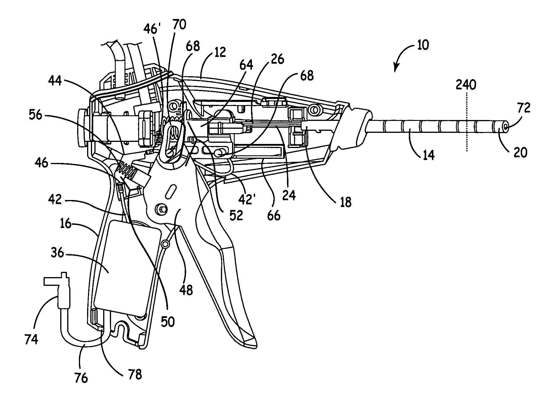
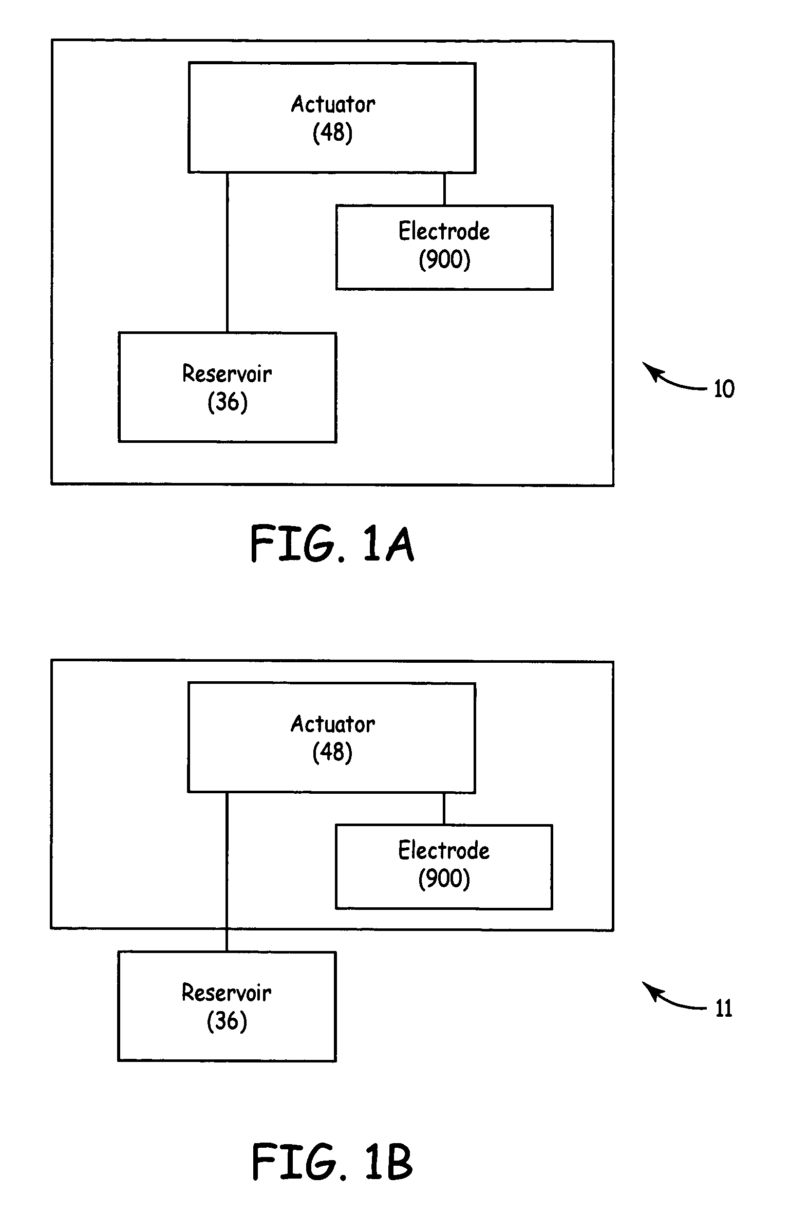
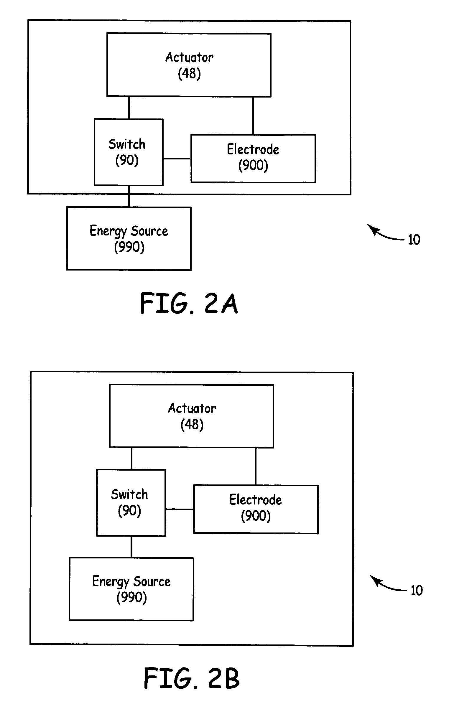
TUNA device with integrated saline reservoir
a technology of saline reservoir and tuna, which is applied in the field of tissue ablation methods and equipment, can solve the problems of limited power delivered and speed of lesion formation in dry electrode approaches, and the complexity of such as tuna, is more complex than traditional dry electrode tissue ablation, and achieves the effect of simplifying wet electrode tissue ablation procedures and simplifying dry electrode techniques
- Summary
- Abstract
- Description
- Claims
- Application Information
AI Technical Summary
Benefits of technology
Problems solved by technology
Method used
Image

Examples
Embodiment Construction
[0026]In the following description, reference is made to the accompanying drawings that form a part hereof, and in which are shown by way of illustration several specific embodiments of the invention. It is to be understood that other embodiments of the invention are contemplated and may be made without departing from the scope or spirit of the present invention. The following detailed description, therefore, is not to be taken in a limiting sense.
[0027]The invention, in various embodiments, relates to methods, apparatuses, and systems employing wet electrode technology. In various embodiments, the wet electrode technology may be applied to TUNA procedures, devices and systems. Various patents and patent applications that discuss wet electrode technology and TUNA include:
[0028]
U.S. Pat. No. 6,849,073, Apparatus and method for creating, maintaining,and controlling a virtual electrode used for the ablation of tissueU.S. Pat. No. 6,623,515, Straight needle apparatus for creating a virt...
PUM
 Abstract
Description
Claims
Application Information