Multidirectional pivoting bone screw and fixation system

a bone screw and multi-directional technology, applied in the field of orthopaedics and spinal surgery, can solve problems such as difficulty in providing secure connection between spinal support rods

Inactive Publication Date: 2008-01-29
WARSAW ORTHOPEDIC INC
View PDF29 Cites 177 Cited by
  • Summary
  • Abstract
  • Description
  • Claims
  • Application Information

AI Technical Summary

Problems solved by technology

It is difficult to provide secure connection between the spinal support rod and these connecting bolts at various angles, and where there are differing distances between the rod and bolts and different heights relative to these components.

Method used


Image

  • Multidirectional pivoting bone screw and fixation system
  • Multidirectional pivoting bone screw and fixation system
  • Multidirectional pivoting bone screw and fixation system

Examples


Embodiment Construction

[0031]Specific language is used in the following description to publicly disclose the invention and to convey its principles to others. No limits on the breadth of the patent rights based simply on using specific language are intended. Also included are any alterations and modifications to the description that should normally occur to one of average skill in this technology.

[0032]This application incorporates by reference the following U.S. patent applications co-owned with the present application: Ser. No. 09 / 526,104, filed Mar. 15, 2002 for SPINAL IMPLANT CONNECTION ASSEMBLY; Ser. No. 09 / 694,703, filed Oct. 23, 2000 for SIX AXIS CONNECTOR FOR SPINAL FIXATION; Ser. No. 09 / 694,702, filed Oct. 23, 2000 for TAPER-LOCKED ADJUSTABLE CONNECTOR; and Ser. No. 09 / 694,291, filed Oct. 23, 2000 for SPINAL IMPLANT CONNECTION ASSEMBLY.

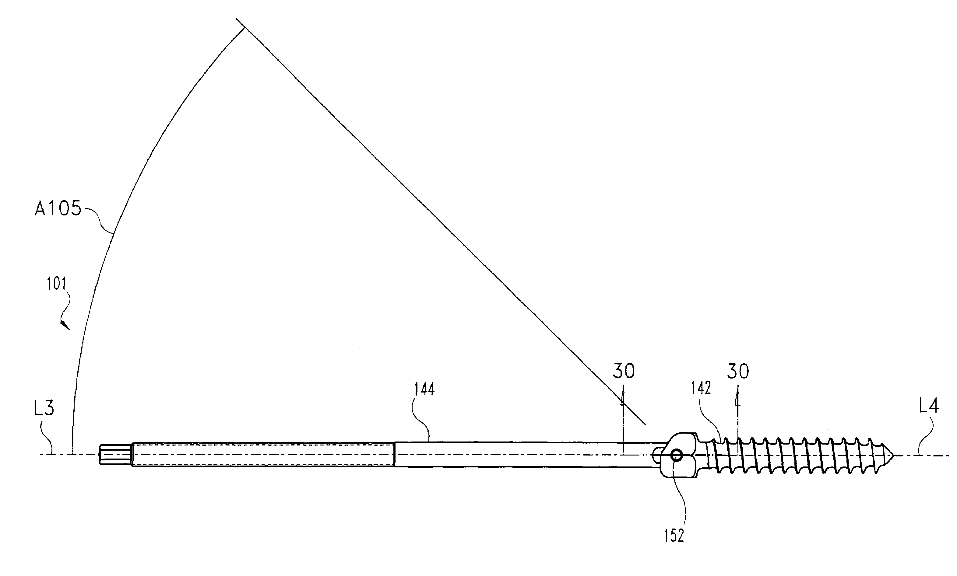
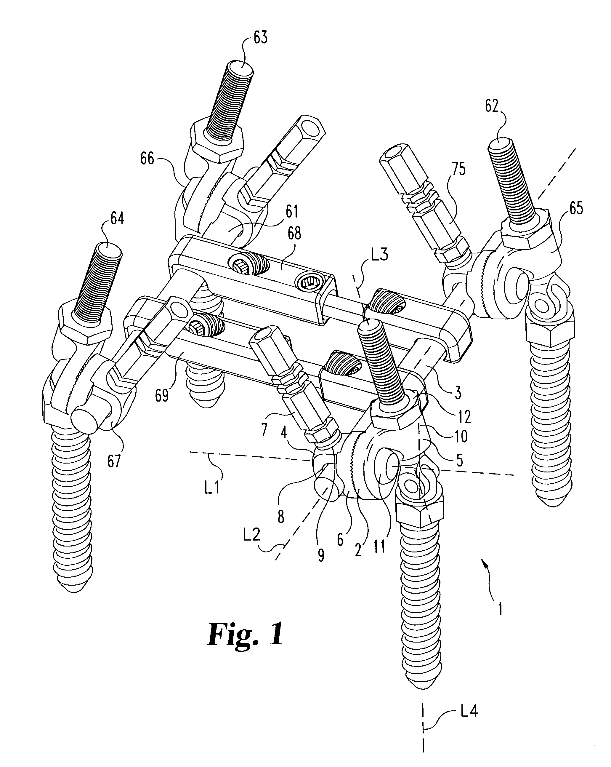
[0033]A bone bolt 1 according to one embodiment of the invention is shown as part of a larger spinal implant system in FIG. 1. Bone bolt 1 is shown attached to a c...


PUM


Abstract

A double-jointed bone bolt for use in an apparatus for maintaining vertebra in a desired relationship. The apparatus has a rod that extends substantially along the spine and one or more bone bolts. At least one of the bone bolts is double jointed. The double-jointed bolt has a mounting portion with a hook or coarse threads to engage a vertebra, and the mounting portion is attached to a pivot post in a manner that allows the pivot post to be rotatable about a common axis in respect to the mounting portion. The pivot post of the bone bolt is then pivotally attached to a connector portion of the bone bolt that has machine threads upon which a surgeon may attach a clamp. The clamp has a second bolt and an arm. The second bolt holds the rod and the arm to the clamp. The second bolt has a first channel to attach to the rod, while the arm has a second channel to attach the double-jointed bone bolt.

Description

CROSS REFERENCE TO RELATED APPLICATIONS[0001]This application is a continuation in part of and claims priority to U.S. patent application Ser. No. 09 / 941,153, filed Aug. 28, 2001 now abandoned which is a continuation of U.S. patent application Ser. No. 09 / 526,435, filed Mar. 15, 2000, now issued as U.S. Pat. No. 6,309,391, which is incorporated herein by reference.FIELD OF THE INVENTION[0002]This invention relates to orthopedics and spinal surgery, and more particularly relates to a double-hinged bone screw to accommodate the differences in position of adjacent bolts implanted in adjacent vertebrae, which bolts are all mounted to a common spinal rod.BACKGROUND[0003]Spinal implant systems provide a rod for supporting the spine and properly positioning components of the spine for various treatment purposes. Bolts or screws are typically secured into the vertebrae for connection to a supporting rod. These bolts must frequently be positioned at various angles due to the anatomical struc...

Claims


Application Information

Patent Timeline
Patent Type & Authority Patents(United States)
IPC IPC(8): A61B17/56A61B17/70
CPCA61B17/7035A61B17/7037A61B17/7038A61B17/7041A61B17/7049
Inventor CRANDALL, DENNISMORRISON, MATTHEW M.STROHKIRCH, TERRANCE
Owner WARSAW ORTHOPEDIC INC
Why Eureka
Try Eureka