Apparatus for pyrolyzing tire shreds and tire pyrolysis systems

a technology of pyrolysis system and tire shred, which is applied in the direction of lighting and heating apparatus, furnaces, muffle furnaces, etc., can solve the problems of burying tires, air pollution, and millions of tires every year

a technology of pyrolysis system and tire shred, which is applied in the direction of lighting and heating apparatus, furnaces, muffle furnaces, etc., can solve the problems of burying tires, air pollution, and millions of tires every year

US7329329B2Inactive Publication Date: 2008-02-12RENAISSANCE ENERGY GROUP

Image

  • Apparatus for pyrolyzing tire shreds and tire pyrolysis systems
  • Apparatus for pyrolyzing tire shreds and tire pyrolysis systems
  • Apparatus for pyrolyzing tire shreds and tire pyrolysis systems

Examples


example 1

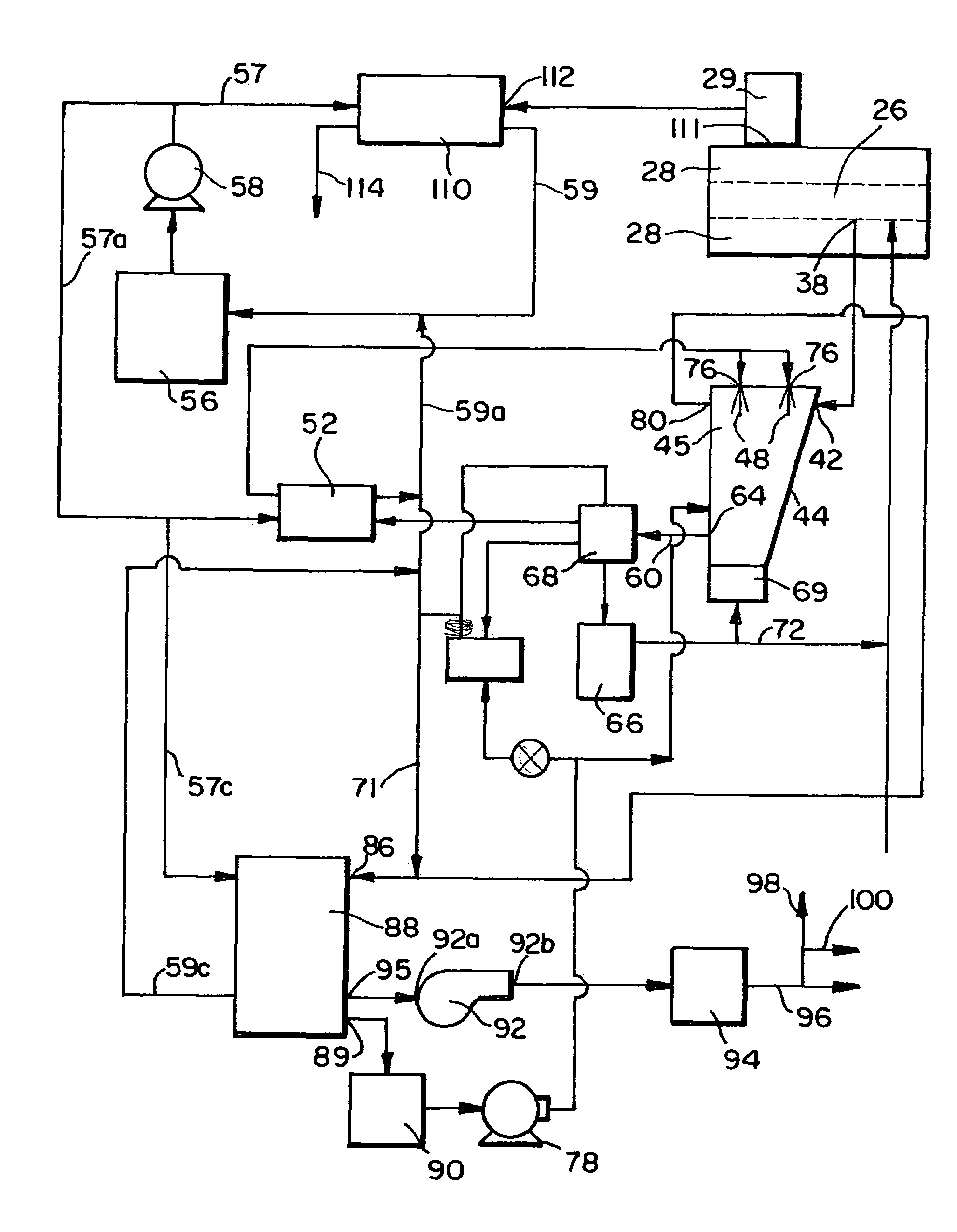
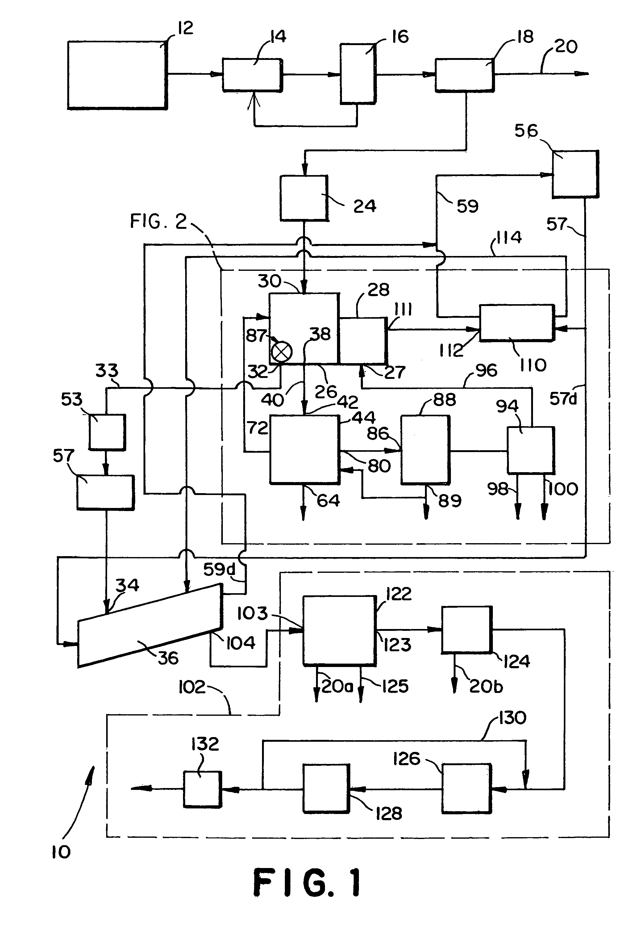
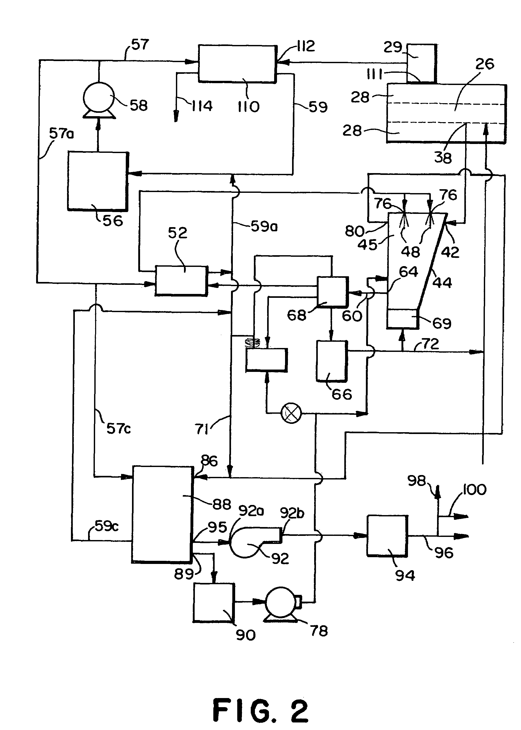
[0069]Tire shreds of a maximum largest dimension of about 2 inches were fed at a rate of about 450 kg / hr to an inlet of a pin auger pyrolysis reactor heated using a firebox temperature of 980° C. The gas used in the firebox is pyrolytic gas taken from the outlet of a final condenser after passing through an oil separator and a final water-cooled condenser and then being further refined using a cyclone separator to remove particulates from the pyrolytic gas. The oil separator included oil sprayers for removing particulate in the hydrocarbon containing gas stream. The elements of the gases within the pyrolytic gas are shown below in Table 1. The composition of the effluent gas is also shown in Table 1 after burning. The effluent gas was cooled and passed into a cooling auger as described below. “ND” in Table 1 indicates a non-detectible amount of less than 0.001% by volume.

[0070]

TABLE 1PyrolyticEffluentGasesGas (vol. %)Gas (vol. %)Nitrogen1.9372.0+Oxygen0.459.0Carbon Dioxide6.05.5Carb...


PUM

PropertyMeasurementUnit
thicknessaaaaaaaaaa
temperatureaaaaaaaaaa

Abstract

Tire pyrolysis systems and processes are provided which include feeding tire shreds to a pyrolysis reactor, pyrolyzing the shreds in a pyrolysis reactor to produce a hydrocarbon-containing gas stream and carbon-containing solid, removing the carbon-containing solid from the reactor, directing the hydrocarbon-containing gas stream into a separator, contacting the hydrocarbon-containing gas stream with an oil spray in the separator thereby washing particulate from the hydrocarbon-containing gas stream and condensing a portion of the gas stream to oil, removing and cooling the oil from the separator, directing non-condensed gas from the gas stream away from the separator, and directing a portion of the cooled oil removed from the separator to an inlet of the separator for use as the separator oil spray. A process is also provided in which solids from the pyrolysis reactor are directed to an auger having a pressure which is greater than the pressure in the pyrolysis reactor, and in which non-condensed gas from the gas stream after condensing a portion of the gas is directed to at least one burner in heat exchange relation with the pyrolysis reactor, and burned to heat the reactor and generate an effluent flue gas, a portion of which effluent flue gas is cooled and injected into the auger which is a trough auger in one embodiment.

Description

CROSS-REFERENCE TO RELATED APPLICATIONS[0001]This application is a divisional of Application Ser. No. 09 / 737,221, filed Dec. 14, 2000 now U.S Pat. No. 6,736,940, entitled Process for Pyrolyzing Tire Shreds and Tire Pyrolysis Systems, the entire disclosure of which is incorporated herein by reference and also claims the benefit of U.S. Provisional Application No. 60 / 170,554 filed Dec. 14, 1999 the entire disclosure of which is also incorporated herein by reference.BACKGROUND OF THE INVENTION[0002]Used tires include materials that, if successfully recycled, may be used for a wide variety of industrial uses. However, due to the difficulty in recycling these materials, millions of tires every-year are worn out and accumulated. Such used tires if burned cause air pollution. Burying tires leads to landfill contamination. Further, since waste tires are bulky, they take up a significant amount of space, even if compacted. Stockpiling of tires and special treatment of tires in landfills furt...

Claims


Application Information

Patent Timeline
12 Feb 2008
Publication
US7329329B2
IPC
C10B1/00; C10B51/00; C10B7/10; C10B47/44; C10B53/07; C10G1/10
CPC
C10B7/10; C10B47/44; C10B53/07; C10G1/10; Y02P20/143
Inventors
MASEMORE, BLAINE; ZARRIZSKI, ROBERT