
Reflection unit having a mirror array, and projection display system employing the same

a technology of mirror array and reflection unit, which is applied in the direction of projectors, television systems, instruments, etc., can solve the problems of limited depth dimension reduction, large size of the entire projection optical system, and difficulty in reducing depth dimension, so as to reduce the depth dimension of the projection display system and maximize the effective image region of the beam

Inactive Publication Date: 2008-02-19
SAMSUNG ELECTRONICS CO LTD
View PDF19 Cites 2 Cited by
  • Summary
  • Abstract
  • Description
  • Claims
  • Application Information

AI Technical Summary

Benefits of technology

[0023]These and / or other aspects and advantages of the present general inventive concept will become apparent and more readily appreciated from the following description of the embodiments, taken in conjunction with the accompanying drawings of which:

Problems solved by technology

However, if the projection optical system is disposed at a center of the screen, reduction of the depth dimension of the square pendulum of the beam bundle from the projection optical system is limited.
However, there is a difficulty in reducing the depth dimension, since the screen is large and a. That is, there is a trend in which the entire projection optical system is increased in size in order to increase the size of the screen.
However, there is a technological difficulty in reducing the size of the entire projection optical system while reducing the depth dimension of the projection display system.
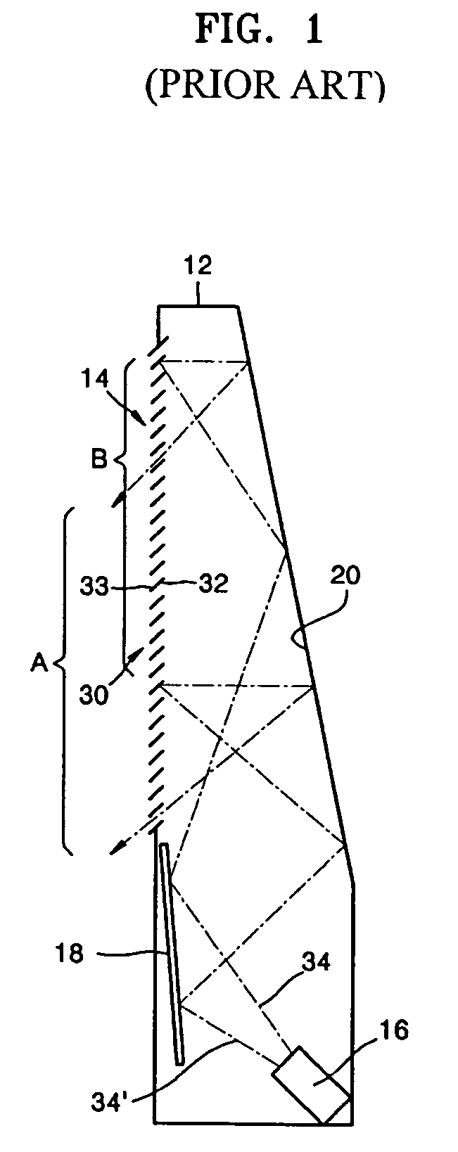
The projection display system of FIG. 1 has a disadvantage in that a contrast deteriorates as a result of the image being reflected twice from the second reflection surface 20 to be incident twice on the screen 14.
Since the effective image region (A) is different from a region (B) at which the image is primarily reflected on the second reflection mirror 20, there is a disadvantage in that an effective screen size is reduced compared to an actual screen size.

Method used


Image

  • Reflection unit having a mirror array, and projection display system employing the same
  • Reflection unit having a mirror array, and projection display system employing the same
  • Reflection unit having a mirror array, and projection display system employing the same

Examples


Embodiment Construction

[0032]Reference will now be made in detail to the embodiments of the present general inventive concept, examples of which are illustrated in the accompanying drawings, wherein like reference numerals refer to the like elements throughout. The embodiments are described below in order to explain the present general inventive concept while referring to the figures.

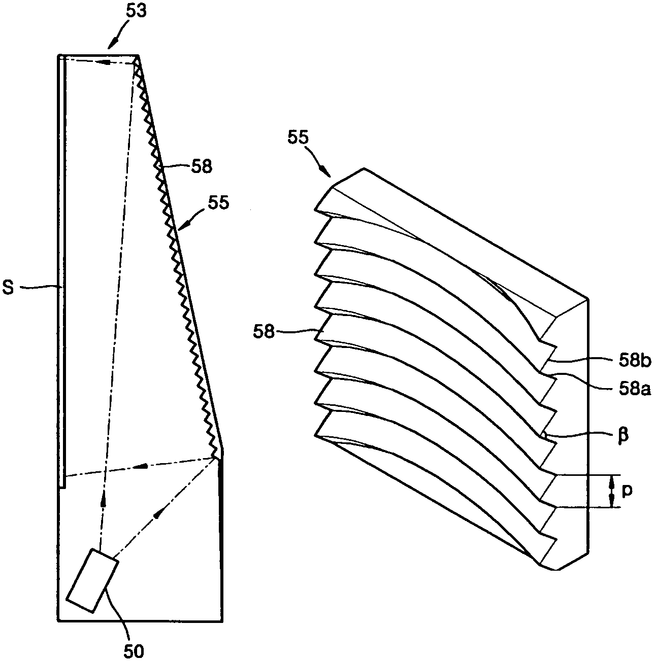
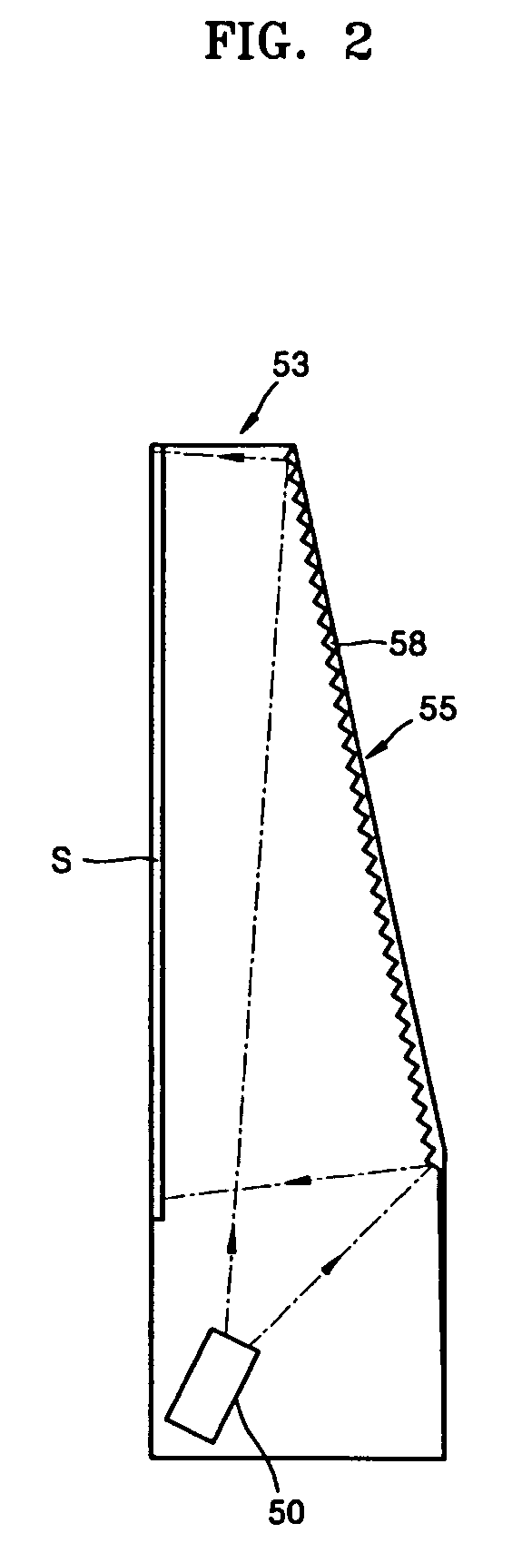
[0033]FIG. 2 is a schematic view illustrating a projection display system according to an embodiment of the present general inventive concept.

[0034]Referring to FIG. 2, the projection display system includes an illumination projecting system 50 to form an image, to magnify the image, and to project the image, and a cabinet 53 including a screen (S).

[0035]The illumination projecting system 50 includes a light source to radiate light. The illumination projecting system 50 magnifies and projects the image, which is formed in a display device, such as a cathode ray tube (CRT), a digital lighting processor (DLP), or a Liquid Cryst...


PUM


Abstract

A projection display system includes a screen, an illumination projecting system to form an image using light radiated by a light source, to magnify the image, and to project the image along a rear side of the screen, and a reflection unit having an array of unit mirrors to reflect the image received from the illumination projecting system onto the screen, each of the unit mirrors having a first sloped reflection surface and a second reflection surface adjacent to the first reflection surface having a predetermined angle therebetween.

Description

CROSS-REFERENCE TO RELATED APPLICATIONS[0001]This application claims priority from Korean Patent Application No. 200448933, filed on Jun. 28, 2004, in the Korean Intellectual Property Office, the disclosure of which is incorporated herein in its entirety by reference.BACKGROUND OF THE INVENTION[0002]1. Field of the Invention[0003]The present general inventive concept relates to a reflection unit having a mirror array and a projection display system employing the same, and more particularly, to a reflection unit and a projection display system in which a mirror array is provided to maximize a reflection region of a beam reflected from the mirror array toward a screen, thereby achieving a reduced depth dimension for the projection display system.[0004]2. Description of the Related Art[0005]In a projection display system, a display element controls light exiting from a lamp light source to form a color image having a plurality of pixels, and the color image is magnified and projected t...

Claims


Application Information

Patent Timeline
Patent Type & Authority Patents(United States)
IPC IPC(8): G03B21/60G03B21/00G03B21/28G03B21/56G03B21/10G03B21/62
CPCG03B21/10G03B21/28G03B21/625H04N5/74
Inventor CHO, KUN-HOBORODOULINE, ALEXEINOH, JI-WHANSOKOLOV, KIRILL
Owner SAMSUNG ELECTRONICS CO LTD
Learn More